TL;DR#
3D room layout estimation uses multiple images but suffers from multi-view geometry complexities, needing camera info, image matching, and triangulation. Recent 3D models like DUSt3R changed things from multi-step to single-step processing. Still, multi-view datasets are scarce, leading to an open problem: wide-baseline sparse-view SfM. New models offer solutions. To that end, This paper uses DUSt3R for multi-view room layout, a natural solution.
This paper introduces Plane-DUSt3R, a new method leveraging DUSt3R for multi-view room layout. It fine-tunes DUSt3R on Structure3D to estimate structural planes, generating uniform results with one post-processing step and 2D detections. Unlike single-view methods, Plane-DUSt3R handles multiple views, streamlining the process and reducing errors. It improves on synthetic datasets and proves robust in-the-wild with different image styles.
Key Takeaways#
Why does it matter?#
This paper introduces a novel multi-view layout estimation method, offering a new approach to 3D scene understanding and robotic navigation. It addresses the challenges of sparse-view SfM and generalizes well to diverse datasets, opening new research directions in unposed multi-view 3D reconstruction.
Visual Insights#

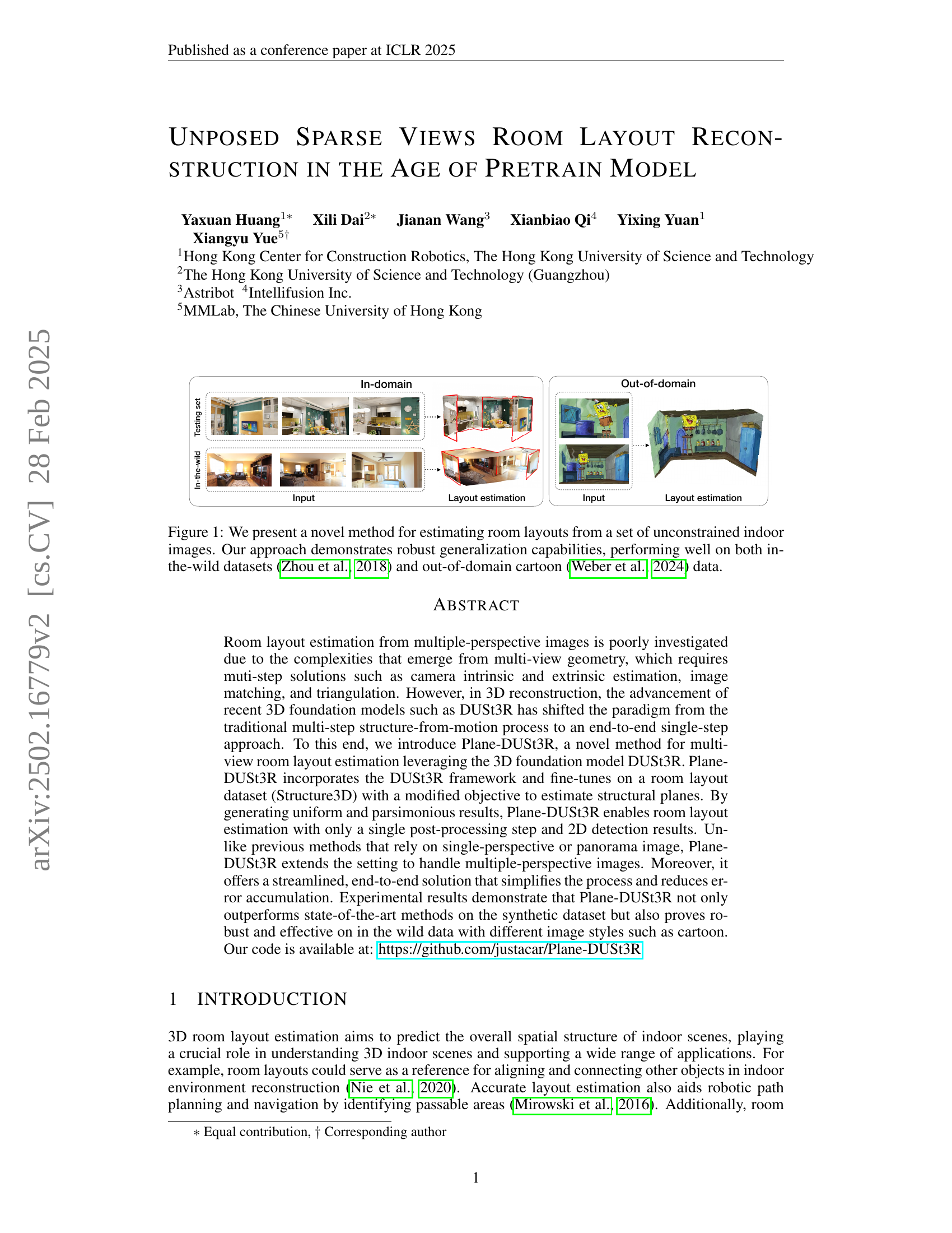
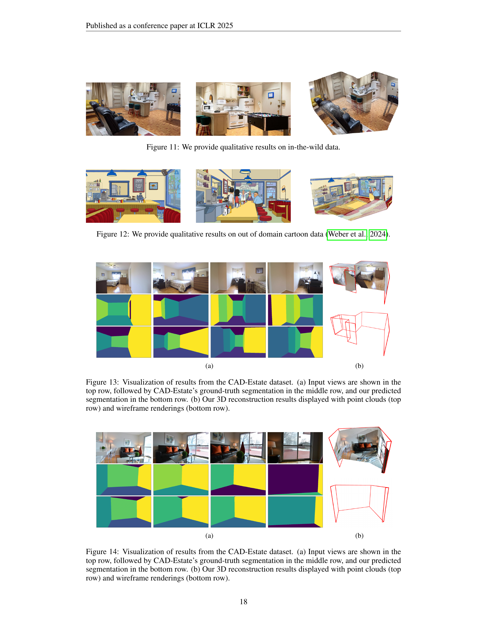
🔼 Figure 1 showcases the effectiveness of a novel room layout estimation method. The figure visually demonstrates the method’s ability to accurately reconstruct room layouts from multiple, unconstrained indoor images. Importantly, it highlights the model’s robustness and generalization capabilities by successfully processing both realistic images from in-the-wild datasets (as seen in the left image group) and significantly different, cartoon-style images from an out-of-domain dataset (as seen in the right image group). This showcases the method’s ability to work effectively across diverse image styles and data sources.
read the caption
Figure 1: We present a novel method for estimating room layouts from a set of unconstrained indoor images. Our approach demonstrates robust generalization capabilities, performing well on both in-the-wild datasets (Zhou et al., 2018) and out-of-domain cartoon (Weber et al., 2024) data.
| Method | re-IoU(%) | re-PE(%) | re-EE | re-RMSE | 3D-precision(%) | 3D-recall(%) |
|---|---|---|---|---|---|---|
| Noncuboid + MASt3R | 74.51 | 8.57 | 12.72 | 0.4831 | 37.00 | 43.39 |
| Noncuboid + GT pose | 75.93 | 7.97 | 11.37 | 0.4457 | 46.96 | 50.59 |
| Ours (metric) | 75.34 | 8.60 | 10.83 | 0.4388 | 48.98 | 45.35 |
| Ours (aligned) | 76.84 | 7.82 | 9.53 | 0.4099 | 52.63 | 48.37 |
🔼 Table 1 presents a comprehensive quantitative comparison of different methods for 3D room layout estimation on the Structure3D dataset. It shows the performance of various methods across multiple metrics, including 2D metrics (Intersection over Union (IoU), Pixel Error (PE), Edge Error (EE), and Root Mean Square Error (RMSE)) and 3D metrics (3D precision and 3D recall). The table enables a detailed analysis of the accuracy and effectiveness of each method in predicting room layouts.
read the caption
Table 1: Quantitative results on Structure3D dataset.
In-depth insights#
Sparse View SfM#
Sparse View Structure from Motion (SfM) presents significant challenges in 3D reconstruction. It is primarily due to the limited data available. This makes accurate camera pose estimation and feature matching difficult. Traditional SfM pipelines often struggle with sparse views. They heavily rely on robust feature detection and matching across multiple images. The challenge arises from the potential for ambiguous or incorrect matches. Such errors can lead to drifting and inaccurate reconstructions. Recent advancements in deep learning offer promising solutions for sparse view SfM. The advancements include neural networks capable of inferring depth and camera pose from limited inputs. These methods often utilize learned priors and regularization techniques to constrain the reconstruction process. This helps to mitigate the ambiguities inherent in sparse data. Key research directions involve developing robust feature descriptors that are invariant to viewpoint changes. Effective strategies for outlier rejection are also important, especially when dealing with noisy or incomplete data. Additionally, exploring techniques for incorporating semantic information. This can further improve the accuracy and completeness of reconstructions from sparse views.
Plane-DUSt3R#
Plane-DUSt3R is introduced as a novel method for multi-view room layout estimation, leveraging the 3D foundation model DUSt3R. It incorporates the DUSt3R framework and fine-tunes on a room layout dataset (Structure3D) with a modified objective to estimate structural planes. By generating uniform and parsimonious results, Plane-DUSt3R enables room layout estimation with only a single post-processing step and 2D detection results. Unlike previous methods that rely on single-perspective or panorama image, Plane-DUSt3R extends the setting to handle multiple-perspective images. It offers a streamlined, end-to-end solution that simplifies the process and reduces error accumulation, demonstrating state-of-the-art performance on synthetic datasets and robustness on in-the-wild data with diverse image styles, including cartoons.
No Camera Poses#
The idea of “no camera poses” in the context of room layout reconstruction represents a significant leap in the field. It implies the ability to infer the 3D structure of a room from multiple images without needing prior knowledge of the camera’s position or orientation for each image. This is valuable because in real-world scenarios, obtaining precise camera poses can be difficult or impossible. This approach usually leverages advanced techniques such as simultaneous localization and mapping (SLAM) or structure from motion (SFM), potentially enhanced by deep learning to estimate camera parameters and the 3D layout jointly. By eliminating the need for pre-calibration, this method increases the flexibility and applicability of room layout reconstruction systems, especially in unstructured environments or when dealing with legacy image data. The success of such methods hinges on robust algorithms capable of handling noisy or incomplete data and accurately estimating the geometric relationships between different viewpoints.
Plane Extraction#
While the provided document doesn’t explicitly have a ‘Plane Extraction’ heading, the paper’s core revolves around reconstructing room layouts by identifying and utilizing planar surfaces. The method, Plane-DUSt3R, heavily relies on extracting meaningful planes from 3D point clouds generated from multiple images. This implicit plane extraction process differs from traditional methods, where planes are detected directly from images. Instead, Plane-DUSt3R is finetuned to predict pointmaps representing only structural planes (walls, floors, ceilings), thereby filtering out irrelevant details and guiding the 3D reconstruction. A key challenge lies in establishing correspondences between planes observed in different views, particularly with sparse views. This is addressed through the DUSt3R framework, which enables robust reconstruction even without explicit camera pose information. To further refine the plane parameters, the method employs a post-processing step that leverages 2D plane detections to guide parameter extraction from the pointmap, improving the accuracy and parsimony of the plane representation. The entire pipeline aims to achieve a simplified and streamlined end-to-end solution that leverages both 3D vision and 2D image understanding. The reconstruction with plane benefits and outperforms the other architectures.
Generalization#
Based on the paper, generalization is a critical aspect for the proposed room layout reconstruction method. The method should not only perform well on the specific synthetic dataset it was trained on (Structure3D), but also demonstrate robustness and adaptability to real-world data (in-the-wild datasets) and scenarios with different image styles (e.g., cartoon data). This indicates the importance of the method’s ability to handle variations in image quality, lighting conditions, object arrangements, and even artistic representations of indoor environments. Achieving good generalization suggests that the method has learned underlying structural principles rather than overfitting to the specifics of the training data. The robustness is further confirmed by the experiment on CAD-estate, ensuring the pipeline to be effective. This ability to generalize is essential for practical applications where the method would encounter diverse and unseen indoor scenes.
More visual insights#
More on figures

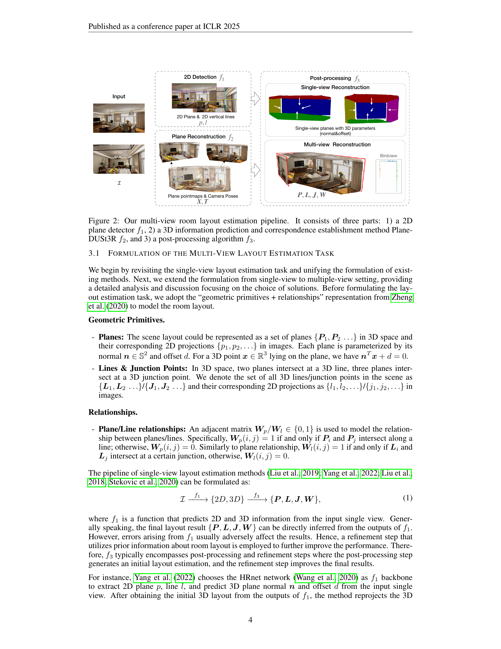
🔼 This figure illustrates the three-stage pipeline for multi-view room layout estimation. The first stage uses a 2D plane detector (f1) to identify planar regions in each input image. The second stage employs Plane-DUSt3R (f2), a modified version of the DUSt3R 3D reconstruction model, to predict 3D information from the 2D detections and establish correspondences between planes across multiple views. The final stage involves a post-processing algorithm (f3) that refines the 3D layout by merging corresponding planes and resolving inconsistencies.
read the caption
Figure 2: Our multi-view room layout estimation pipeline. It consists of three parts: 1) a 2D plane detector f1subscript𝑓1f_{1}italic_f start_POSTSUBSCRIPT 1 end_POSTSUBSCRIPT, 2) a 3D information prediction and correspondence establishment method Plane-DUSt3R f2subscript𝑓2f_{2}italic_f start_POSTSUBSCRIPT 2 end_POSTSUBSCRIPT, and 3) a post-processing algorithm f3subscript𝑓3f_{3}italic_f start_POSTSUBSCRIPT 3 end_POSTSUBSCRIPT.

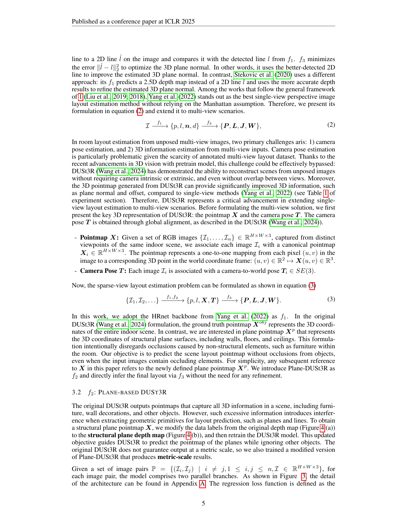
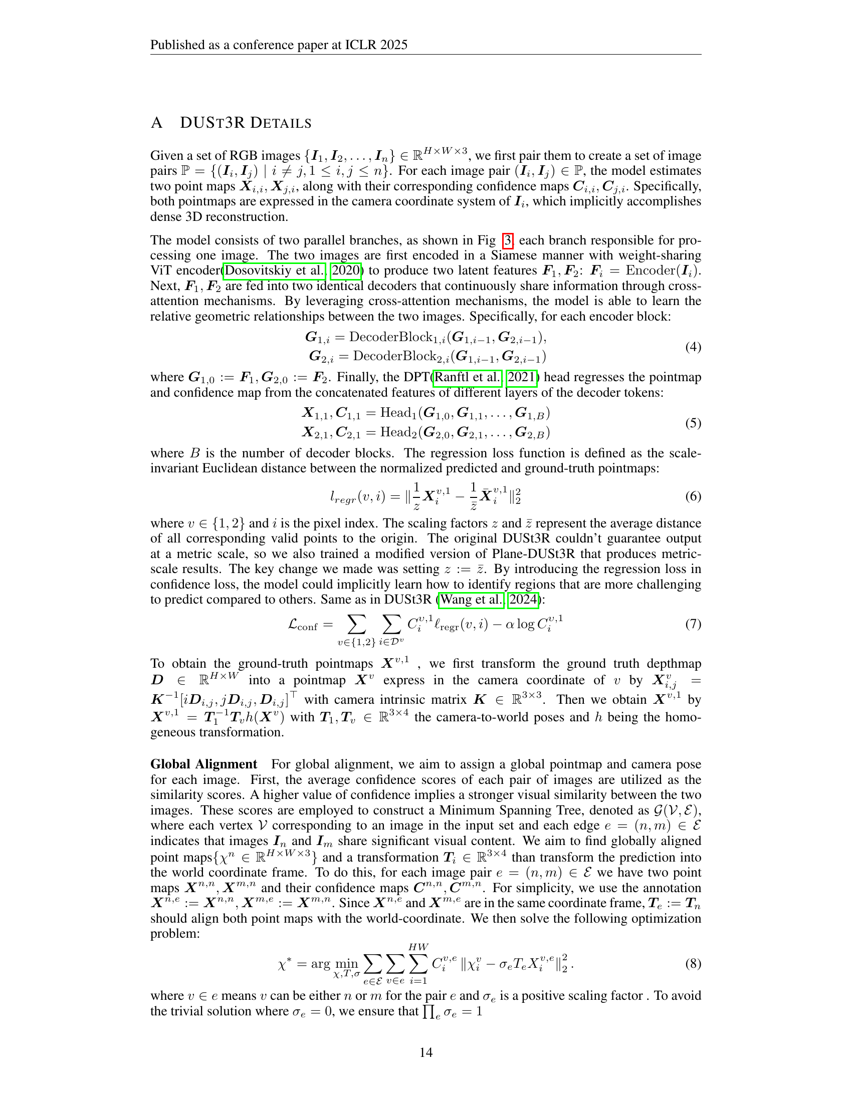
🔼 The Plane-DUSt3R architecture is a modified version of the DUSt3R architecture. The core components remain the same: a Vision Transformer (ViT) encoder, a transformer decoder, and two regression heads. However, a key difference is that Plane-DUSt3R is fine-tuned on a depth map that has been pre-processed to remove occlusions caused by objects within the room. This allows Plane-DUSt3R to focus solely on the structural planes, such as walls, floors, and ceilings, simplifying the layout prediction task. The figure visually depicts the architecture of Plane-DUSt3R, emphasizing its similarity to DUSt3R while highlighting the modifications made for the specific purpose of room layout estimation.
read the caption
Figure 3: Plane-DUSt3R architecture remains identical to DUSt3R. The transformer decoder and regression head are further fine-tuned on the occlusion-free depth map (see Figure 4).

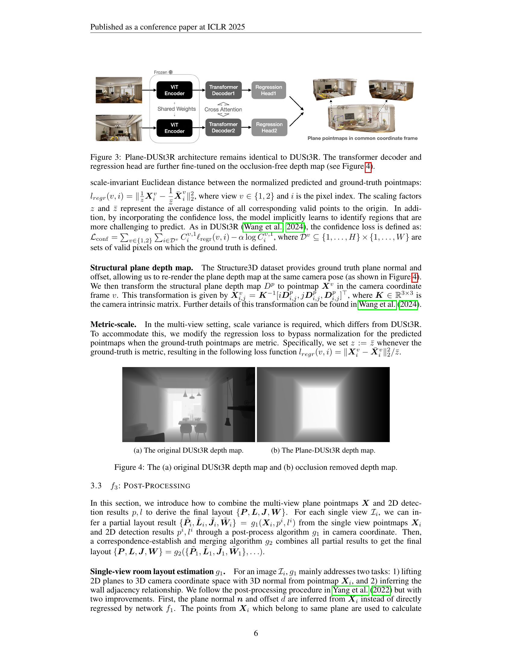
🔼 This figure shows a comparison of depth maps generated by two different methods. (a) displays the depth map produced by the original DUSt3R model, which contains information about all 3D elements within the scene, including both structural elements (walls, floors, ceilings) and non-structural objects (furniture). This comprehensive depth map can be complex and noisy. The goal of Plane-DUSt3R is to simplify this for better room layout estimation.
read the caption
(a) The original DUSt3R depth map.

🔼 Figure 4(b) shows the depth map generated by the Plane-DUSt3R model. Unlike the original DUSt3R depth map (shown in Figure 4(a)), this depth map focuses exclusively on structural planes (walls, floors, ceilings), effectively removing occlusions caused by objects or furniture. This processed depth map serves as crucial input for subsequent steps in the room layout estimation pipeline, leading to a more accurate and streamlined layout prediction.
read the caption
(b) The Plane-DUSt3R depth map.

🔼 This figure compares the depth maps generated by the original DUSt3R model and the modified Plane-DUSt3R model. (a) shows the depth map produced by DUSt3R which includes various objects and occlusions within the scene. (b) displays the depth map generated by Plane-DUSt3R after modifications. The key difference is that Plane-DUSt3R’s depth map focuses exclusively on structural planes (walls, floor, ceiling), effectively removing occlusions from non-structural elements like furniture to improve room layout estimation.
read the caption
Figure 4: The (a) original DUSt3R depth map and (b) occlusion removed depth map.

🔼 Figure 5(a) shows the visualization of the plane projection step in the multi-view room layout estimation pipeline. The input is a set of planes detected in multiple images of the same scene. Each plane is represented by a line segment in the image, and these line segments are then projected onto a common 2D plane (such as the xz plane). This projection simplifies the scene representation, making the subsequent merging process easier. The line segments shown in this figure form the basis for classifying lines as horizontal or vertical before the final merging step. They will then be used in the steps described in (b), (c) and (d) to align and merge them into coherent planes for the final layout.
read the caption
(a) Projected Lines

🔼 This figure shows the results of rotating the line segments representing planes projected onto the x-z plane so that they become approximately horizontal or vertical. This rotation step simplifies the subsequent classification and merging of line segments into complete planes.
read the caption
(b) Rotated Lines

🔼 This figure shows the results of aligning line segments to be either horizontal or vertical after a rotation. This step is part of a multi-view room layout estimation process where the goal is to merge planes from different images to create a unified 3D room layout. The alignment simplifies the merging process by ensuring that line segments representing the same wall are parallel to each other, facilitating their identification and combination.
read the caption
(c) Aligned Lines

🔼 This figure shows the results of merging plane segments to create a unified representation of the room layout. Panel (a) displays the initial projection of plane segments onto the x-z plane. Panel (b) shows the rotation of these segments to be either horizontal or vertical. Panel (c) shows the classification and further alignment of segments. Panel (d) presents the final result of merged planes, with segments of the same plane highlighted with the same color and index. This illustrates the process of combining individual plane segments from multiple views into a consistent 3D room layout.
read the caption
(d) Correspondance

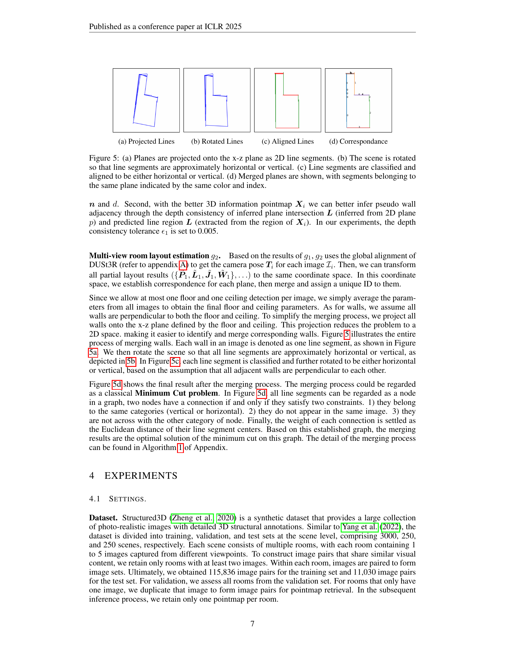
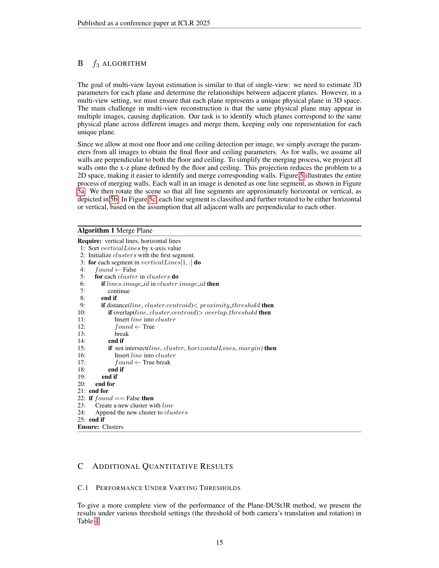
🔼 Figure 5 illustrates the multi-view plane merging process. (a) shows the projection of planes onto the x-z plane, represented as 2D line segments. (b) depicts the scene’s rotation to make these line segments roughly horizontal or vertical. (c) shows classification and alignment of these line segments as either horizontal or vertical. Finally, (d) presents the merged planes with segments of the same plane indicated using a consistent color and index, resolving plane correspondence across multiple images.
read the caption
Figure 5: (a) Planes are projected onto the x-z plane as 2D line segments. (b) The scene is rotated so that line segments are approximately horizontal or vertical. (c) Line segments are classified and aligned to be either horizontal or vertical. (d) Merged planes are shown, with segments belonging to the same plane indicated by the same color and index.

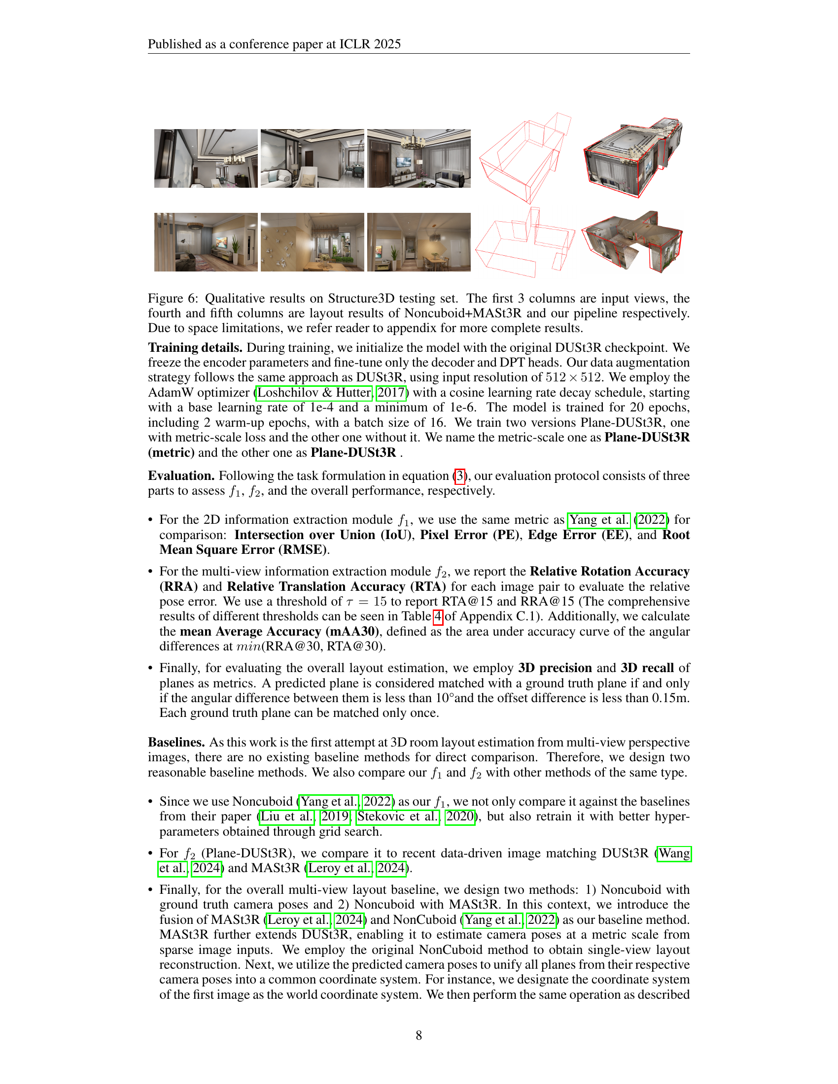
🔼 This figure showcases qualitative results of room layout reconstruction on the Structure3D dataset’s testing set. The first three columns display the input images from multiple viewpoints. The fourth column presents the results obtained using the Noncuboid+MASt3R method. The fifth column shows the results produced by the proposed Plane-DUSt3R pipeline in this paper. Due to space constraints in the publication, additional results are available in the appendix for a more comprehensive evaluation.
read the caption
Figure 6: Qualitative results on Structure3D testing set. The first 3 columns are input views, the fourth and fifth columns are layout results of Noncuboid+MASt3R and our pipeline respectively. Due to space limitations, we refer reader to appendix for more complete results.

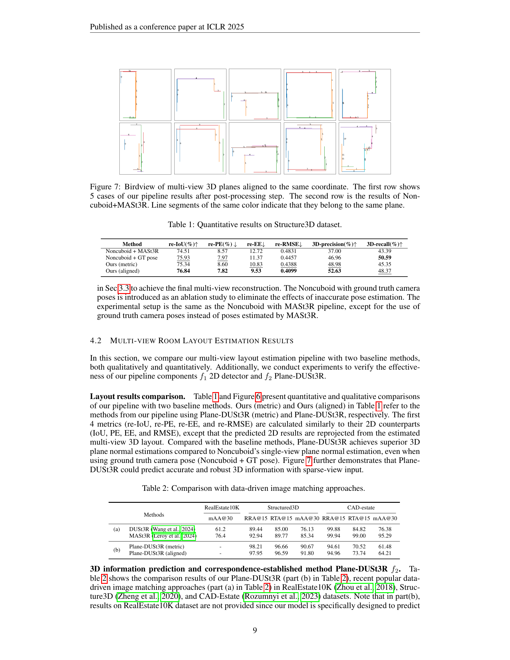
🔼 This figure displays a bird’s-eye view of 3D room layouts generated from multiple images using two different methods. The top row presents five examples of 3D room layouts produced by the proposed pipeline (Plane-DUSt3R), illustrating the pipeline’s ability to reconstruct the spatial structure of rooms from sparse, unconstrained viewpoints. Each plane is represented by a unique color, making it easy to distinguish individual walls, floors, and ceilings in the reconstruction. The bottom row shows five comparative results obtained using a baseline method (Noncuboid+MASt3R), highlighting differences in accuracy and completeness of the room layout reconstruction. The consistent use of color-coding for corresponding planes in both rows enables a direct visual comparison of the two methods’ performance. This visualization effectively demonstrates the superior performance of the proposed Plane-DUSt3R method in handling multi-view scenarios with sparse image data.
read the caption
Figure 7: Birdview of multi-view 3D planes aligned to the same coordinate. The first row shows 5 cases of our pipeline results after post-processing step. The second row is the results of Noncuboid+MASt3R. Line segments of the same color indicate that they belong to the same plane.

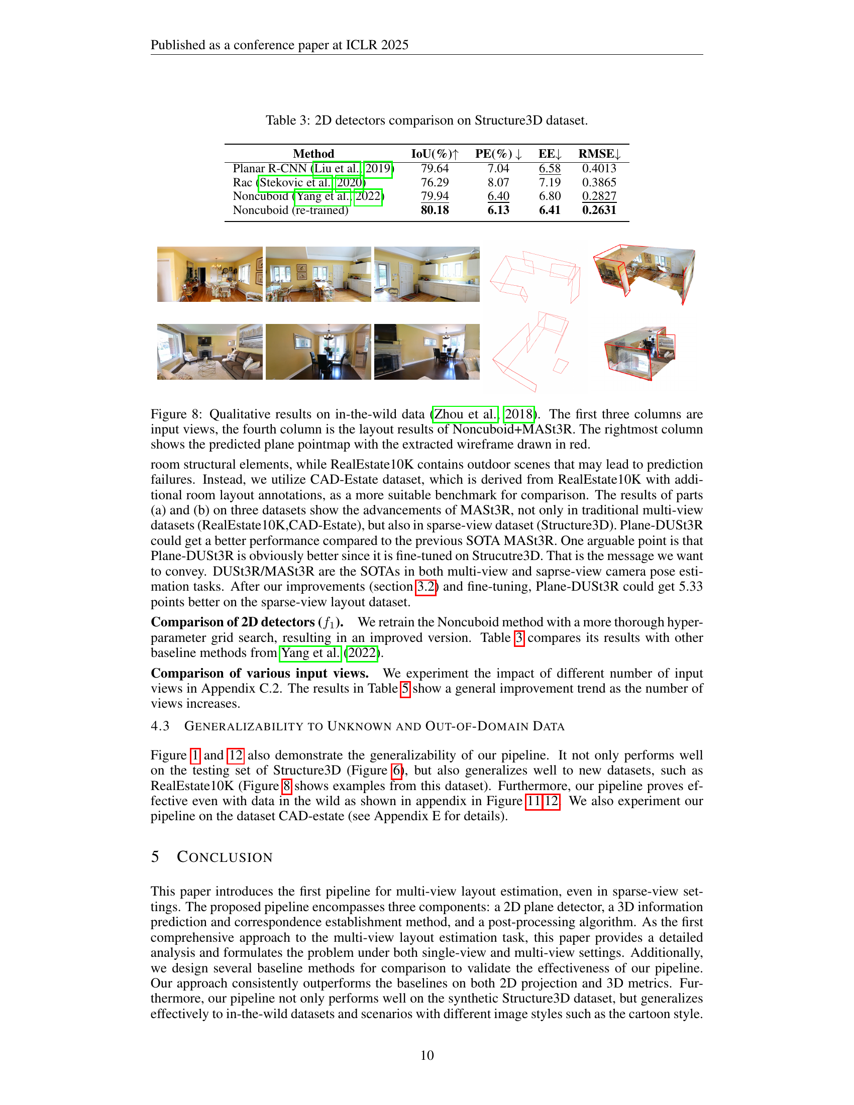
🔼 Figure 8 displays a qualitative comparison of room layout estimations on the ‘in-the-wild’ dataset (Zhou et al., 2018). The figure presents sets of three input images from various viewpoints for each room, followed by the room layout estimated using the Noncuboid+MASt3R method. The final column shows the predicted 3D plane point cloud generated by the proposed method, with the extracted wireframe structure overlaid in red, providing a clear visualization of the planes detected and their spatial relationships within each scene.
read the caption
Figure 8: Qualitative results on in-the-wild data (Zhou et al., 2018). The first three columns are input views, the fourth column is the layout results of Noncuboid+MASt3R. The rightmost column shows the predicted plane pointmap with the extracted wireframe drawn in red.

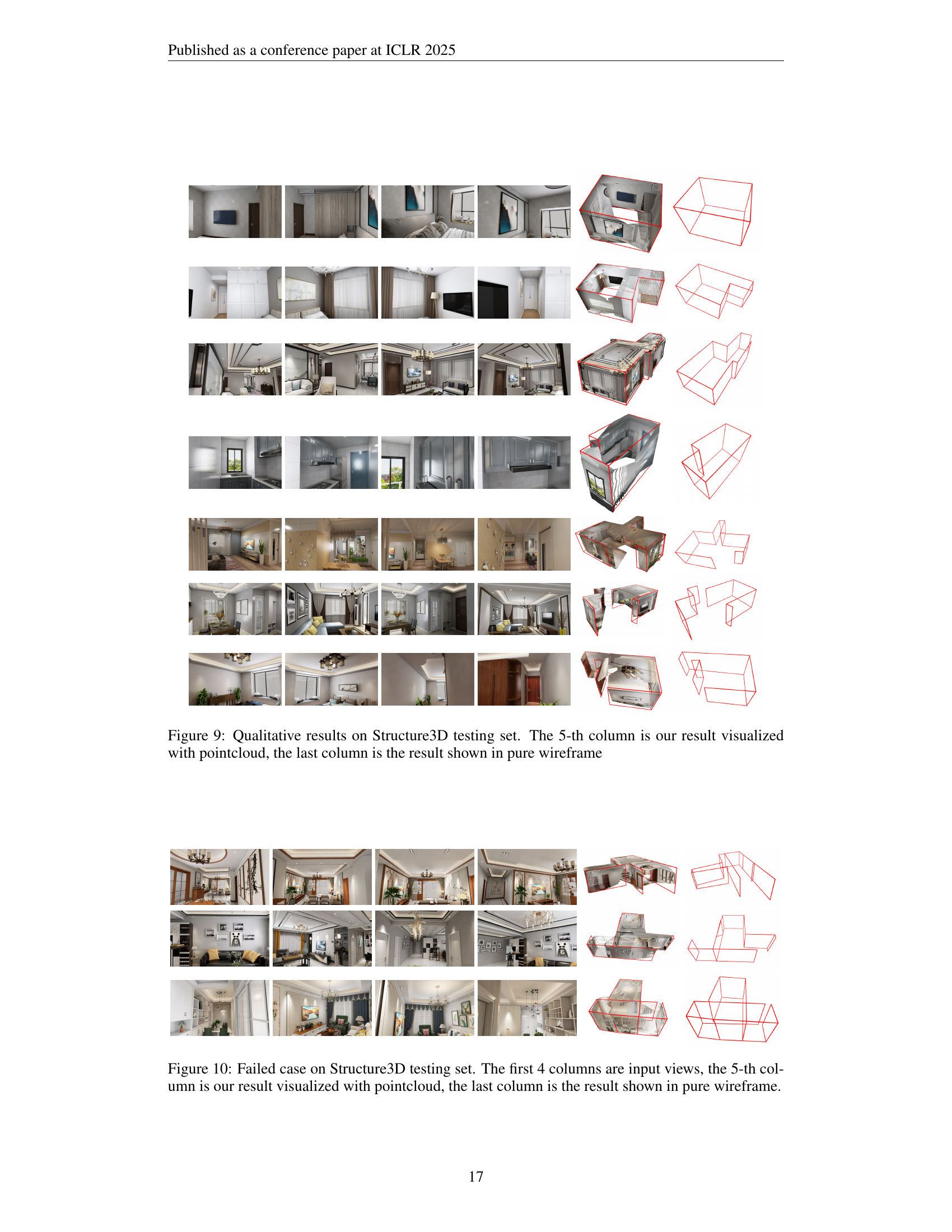
🔼 Figure 9 presents a qualitative comparison of the proposed multi-view room layout estimation method’s performance on the Structure3D test set. Each row shows a different room scene. The first four columns display the input views (multiple perspectives of the same scene). The fifth column shows the 3D reconstruction results using point cloud visualization to represent the room’s layout, demonstrating the method’s ability to accurately estimate the positions of planes representing walls, floors, and ceilings. The final column displays the same results using only the wireframe, providing a simplified representation focusing solely on the geometric structure of the layout and omitting the detailed 3D point cloud.
read the caption
Figure 9: Qualitative results on Structure3D testing set. The 5-th column is our result visualized with pointcloud, the last column is the result shown in pure wireframe
More on tables
| Methods | RealEstate10K | Structured3D | CAD-estate | |||||
|---|---|---|---|---|---|---|---|---|
| mAA@30 | RRA@15 | RTA@15 | mAA@30 | RRA@15 | RTA@15 | mAA@30 | ||
| (a) | DUSt3R (Wang et al., 2024) | 61.2 | 89.44 | 85.00 | 76.13 | 99.88 | 84.82 | 76.38 |
| MASt3R (Leroy et al., 2024) | 76.4 | 92.94 | 89.77 | 85.34 | 99.94 | 99.00 | 95.29 | |
| (b) | Plane-DUSt3R (metric) | - | 98.21 | 96.66 | 90.67 | 94.61 | 70.52 | 61.48 |
| Plane-DUSt3R (aligned) | - | 97.95 | 96.59 | 91.80 | 94.96 | 73.74 | 64.21 | |
🔼 This table presents a comparison of the Plane-DUSt3R model’s performance against other state-of-the-art data-driven image matching approaches on three datasets: RealEstate10K, Structured3D, and CAD-estate. The comparison uses the metrics mAA@30, RRA@15, and RTA@15 to evaluate the accuracy of relative camera pose estimation. This allows for an assessment of the Plane-DUSt3R model’s ability to accurately estimate the relative positions and orientations of cameras in multi-view scenes. The inclusion of three diverse datasets enables a comprehensive evaluation of the model’s robustness and generalization capabilities across different scene complexities and data characteristics.
read the caption
Table 2: Comparison with data-driven image matching approaches.
| Method | IoU(%) | PE(%) | EE | RMSE |
|---|---|---|---|---|
| Planar R-CNN (Liu et al., 2019) | 79.64 | 7.04 | 6.58 | 0.4013 |
| Rac (Stekovic et al., 2020) | 76.29 | 8.07 | 7.19 | 0.3865 |
| Noncuboid (Yang et al., 2022) | 79.94 | 6.40 | 6.80 | 0.2827 |
| Noncuboid (re-trained) | 80.18 | 6.13 | 6.41 | 0.2631 |
🔼 This table presents a comparison of different 2D plane detectors on the Structure3D dataset. The metrics used for comparison include Intersection over Union (IoU), Pixel Error (PE), Edge Error (EE), and Root Mean Square Error (RMSE). These metrics assess the accuracy and precision of each detector in identifying and localizing planar regions within the images. The table helps determine which 2D plane detector is the most effective in terms of accuracy and efficiency for the Structure3D dataset.
read the caption
Table 3: 2D detectors comparison on Structure3D dataset.
| Threshold(Translation & Rotation) | 3D-precision(%) | 3D-recall(%) |
|---|---|---|
| 0.1m, 5° | 34.11 | 31.66 |
| 0.15m, 10° | 52.63 | 48.37 |
| 0.2m, 15° | 64.64 | 59.53 |
| 0.4m, 30° | 82.75 | 76.13 |
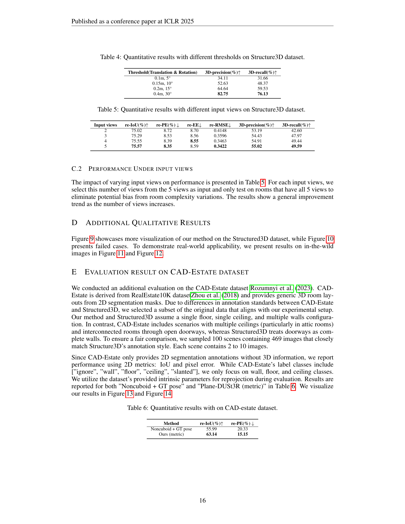
🔼 This table presents a quantitative evaluation of the Plane-DUSt3R model’s performance on the Structure3D dataset under various thresholds for camera translation and rotation. It shows the impact of different thresholds on the accuracy of 3D plane prediction and reconstruction. The metrics used are 3D precision and 3D recall, illustrating the model’s ability to correctly identify and represent planes in the 3D scene based on different thresholds of tolerance. Higher thresholds allow for greater error margins and would likely result in higher recall (more planes detected), but potentially at the cost of lower precision (fewer correctly identified planes).
read the caption
Table 4: Quantitative results with different thresholds on Structure3D dataset.
| Input views | re-IoU(%) | re-PE(%) | re-EE | re-RMSE | 3D-precision(%) | 3D-recall(%) |
|---|---|---|---|---|---|---|
| 2 | 75.02 | 8.72 | 8.70 | 0.4148 | 53.19 | 42.60 |
| 3 | 75.29 | 8.53 | 8.56 | 0.3596 | 54.43 | 47.97 |
| 4 | 75.55 | 8.39 | 8.55 | 0.3463 | 54.91 | 49.44 |
| 5 | 75.57 | 8.35 | 8.59 | 0.3422 | 55.02 | 49.59 |
🔼 This table presents a quantitative analysis of the impact of varying the number of input views on the performance of the room layout estimation model. Specifically, it shows how metrics such as Intersection over Union (IoU), Pixel Error (PE), Edge Error (EE), Root Mean Square Error (RMSE), 3D precision, and 3D recall change as the number of input views increases from 2 to 5. The results are based on the Structure3D dataset, allowing for a detailed assessment of the model’s robustness and efficiency with different data conditions.
read the caption
Table 5: Quantitative results with different input views on Structure3D dataset.
| Method | re-IoU(%) | re-PE(%) |
|---|---|---|
| Noncuboid + GT pose | 55.99 | 20.33 |
| Ours (metric) | 63.14 | 15.15 |
🔼 Table 6 presents a quantitative comparison of room layout estimation results on the CAD-Estate dataset. It compares the performance of the proposed method (Plane-DUSt3R) against a baseline (Noncuboid + GT pose) using two key metrics: Intersection over Union (IoU), measuring the overlap between predicted and ground truth segmentations, and Pixel Error (PE), quantifying the average pixel-wise distance between the predictions and ground truth. The CAD-Estate dataset is chosen because it aligns well with the research method’s focus and assumptions.
read the caption
Table 6: Quantitative results with on CAD-estate dataset.
Full paper#