TL;DR#
Traditional multi-task image coding methods often use multiple task-specific encoder-decoder pairs, leading to high parameter overhead and inefficient bitrate usage. They also face challenges in multi-objective optimization under a unified representation. This paper addresses these issues by focusing on joint human-machine vision. Existing approaches struggle with balancing performance and efficiency across diverse tasks, hindering seamless transitions between human-centric and machine-centric reconstruction.
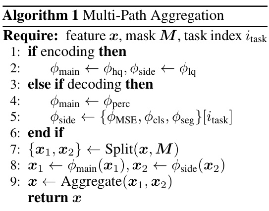
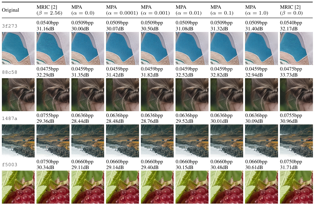
The proposed method, Multi-Path Aggregation (MPA), integrates into existing coding models. MPA uses a predictor to allocate latent features among task-specific paths, maximizing the use of shared features while preserving task-specific ones. A two-stage optimization strategy leverages feature correlations to ease multi-task performance degradation. Experimental results demonstrate that MPA achieves performance comparable to state-of-the-art methods, supporting seamless transitions between human and machine vision tasks with minimal parameter overhead.
Key Takeaways#
Why does it matter?#
This paper is important because it presents a novel and efficient solution for multi-task image coding, addressing the limitations of existing methods by proposing a unified model for joint human-machine vision. It offers a flexible and customizable approach, allowing for seamless transitions between different tasks with minimal parameter overhead. This work opens new avenues for research in efficient multi-task learning and adaptable image coding for various applications.
Visual Insights#

🔼 This figure compares three different paradigms for multi-task coding. (a) Separate pairs shows multiple task-specific encoder-decoder pairs, which are easy to optimize but lead to high parameter and bitrate overhead. (b) Unified representation uses a single encoder for feature extraction and multiple task-specific decoders, improving compression efficiency but still suffering from parametric inefficiency due to multiple decoders. (c) Unified model uses a single encoder and a single decoder with task-oriented reconstruction, aiming for better efficiency and allowing flexible transitions between tasks, but posing challenges in multi-objective optimization.
read the caption
Figure 1: Paradigm comparison for multi-task coding.
🔼 This table presents the results of an ablation study on the complexity of different MLP paths used in the Multi-Path Aggregation (MPA) model. It shows how different MLP path types (Bottleneck, Inverted Bottleneck) affect the performance of different tasks (MSE, Classification, Segmentation) as measured by BD-Rate, Accuracy, and mIoU, respectively. This helps to understand the impact of different path complexities on overall model performance for various downstream tasks.
read the caption
Table 1: Effects of path complexity
In-depth insights#
Multi-Path coding#
Multi-path coding, in the context of image compression for joint human-machine vision, presents a powerful paradigm shift. Instead of using a single, monolithic feature representation, it leverages multiple parallel paths, each specializing in a specific task or aspect of the image. This allows for more efficient allocation of resources, as each path can be optimized independently for its target. The predictor plays a crucial role, dynamically allocating latent features across the paths based on their relative importance for the selected tasks. This dynamic allocation ensures that critical features are prioritized, maximizing the utility of the shared representation while preserving task-specific features. The two-stage optimization strategy further enhances efficiency, minimizing parameter overhead and improving performance. The first stage builds a general model, while the second stage focuses only on the task-specific refinements. This modularity makes it easier to add new tasks without needing to retrain the entire model, ensuring scalability and flexibility. Seamless transition between human and machine-oriented reconstruction capabilities is another significant benefit. Overall, multi-path coding offers a promising avenue for achieving high performance and efficiency in the increasingly complex landscape of joint human-machine vision systems.
Unified framework#
A unified framework in a research paper likely integrates diverse aspects of a problem, offering a holistic solution. This approach contrasts with fragmented solutions that tackle subproblems independently. The advantages of a unified framework are numerous: it simplifies the overall design, reduces redundancy, and promotes synergy among components. A well-designed framework enhances understanding by presenting a cohesive view, improving the clarity of the methodology and results. Data efficiency is another key advantage, as a unified system might require less data for optimal performance. However, complexity in design and implementation can be a significant challenge in a unified framework, potentially requiring more time and expertise. There’s also a risk of reduced modularity, making it harder to isolate and modify specific parts without affecting the entire system. Therefore, a successful unified framework necessitates a careful balance between integration and modularity, and a thorough analysis of trade-offs between complexity and performance gains is crucial for a successful implementation. Thorough validation and a robust testing strategy are essential to ensure reliability and effectiveness. This holistic approach has the potential to significantly enhance the overall efficiency and interpretability of the research, provided that the design and implementation are handled effectively.
Two-stage training#
A two-stage training approach in a research paper likely involves a phased optimization strategy. The first stage might focus on learning generalizable features across multiple tasks using a shared representation, potentially by minimizing a weighted combination of task-specific loss functions. This initial phase aims to establish a robust foundation with a unified model capable of performing multiple tasks at a base level. The second stage is refinement, where the model is fine-tuned by allocating resources to task-specific paths based on their importance in the unified representation. This targeted optimization might involve adding task-specific modules, but the key is that only a fraction of parameters are modified. This limits the increase in complexity and reduces computational costs while significantly improving task-specific performance. The overall goal is to find a balance between generalizability and specialization, leveraging feature correlations across tasks to avoid extensive parameter tuning that could be inefficient and lead to overfitting.
Parameter Efficiency#
Parameter efficiency is a crucial aspect in many machine learning applications, especially those dealing with resource-constrained environments. The paper likely explores techniques to reduce model size while maintaining accuracy. This could involve using model compression methods like pruning, quantization, or knowledge distillation. A key focus might be on the trade-off between parameter reduction and performance degradation. The all-in-one design mentioned suggests a unified model architecture, potentially reducing redundancy and improving efficiency compared to multiple task-specific models. The claim of minimal additional parameters through multi-path aggregation is a strong statement of parameter efficiency. A detailed evaluation of parameter counts, performance metrics (like PSNR, LPIPS, accuracy), and inference speed would be important for assessing the overall efficiency. The two-stage optimization strategy is also an important factor to analyze in regards to computational cost and efficiency gains. The practical implication of lower parameter counts could involve reduced memory requirements, faster training times, and more efficient deployment on edge devices.
Future Extensions#
Future work could explore several promising avenues. Improving the efficiency of MPA is crucial, possibly through specialized operators to reduce computational overhead, or by leveraging more advanced multi-task learning techniques to unify the training process. Investigating the impact of different MLP architectures within MPA, and exploring alternatives to the current predictor mechanism are also important. Further research could analyze the generalizability of MPA across diverse tasks and datasets, perhaps by testing it on more challenging machine vision tasks or incorporating additional visual modalities. Finally, exploring the potential for compression artifact reduction and improving the subjective quality of reconstructions remains a key focus. A thorough investigation into these areas would significantly enhance MPA’s performance and applicability.
More visual insights#
More on figures
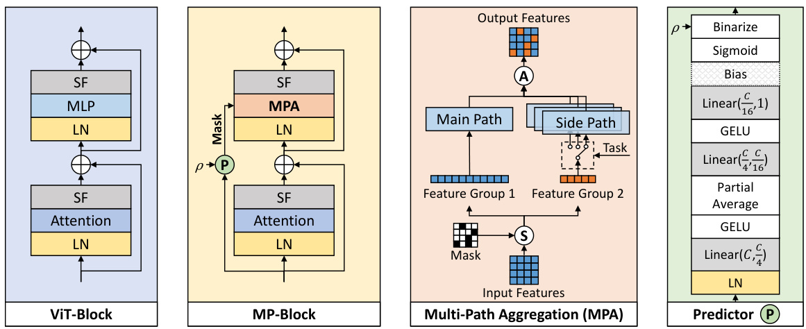
🔼 This figure illustrates the architecture of the proposed Multi-Path Aggregation (MPA) module. It shows how MPA replaces the standard MLP within a Vision Transformer block. The key components are a predictor (P) that generates a mask to split the input features into main and side paths; a splitting operation (S); and an aggregation operation (A) that combines the processed features from both paths. The main path processes generalized features for all tasks, while side paths are specialized for specific tasks. The figure also shows the use of Layer Normalization (LN) and Scaling Factors (SF). Different MLP structures are used in the main and side paths, based on whether high or low bitrate features are processed.
read the caption
Figure 2: The proposed Multi-Path Aggregation (MPA). Compared to typical Vision Transformer (ViT) block [73, 16], original MLP is replaced with MPA. LN and SF are Layer Normalization and Scaling Factors [10]. P, S and A denote predictor, split and aggregation respectively. C represents the number of input channels. p is the ratio penc in the encoder or the ratio pdec in the decoder.
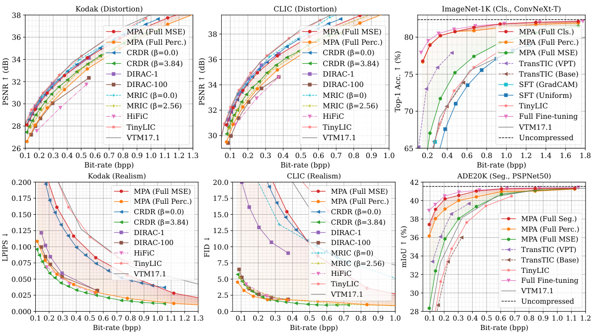
🔼 This figure presents a comparison of the multi-task performance of the proposed MPA method against several state-of-the-art (SOTA) methods. The performance is evaluated across four different tasks: image compression with distortion and realism metrics (using Kodak and CLIC datasets); classification (using the ImageNet-1K dataset); and semantic segmentation (using the ADE20K dataset). The results are shown in terms of rate-distortion (R-D) curves and rate-perception (R-P) curves (where applicable). The solid lines indicate variable-rate models, while dashed lines represent single-rate models for comparison. The colored areas highlight the flexibility of MPA’s adjustable range to accommodate diverse task preferences. Overall, MPA demonstrates competitive performance, outperforming others in many cases, especially at lower bitrates.
read the caption
Figure 3: Multi-task performance. The curves of variable-rate models are plotted as solid lines, while dashed lines are for single-rate models. Colored areas represent the adjustable range of MPA.

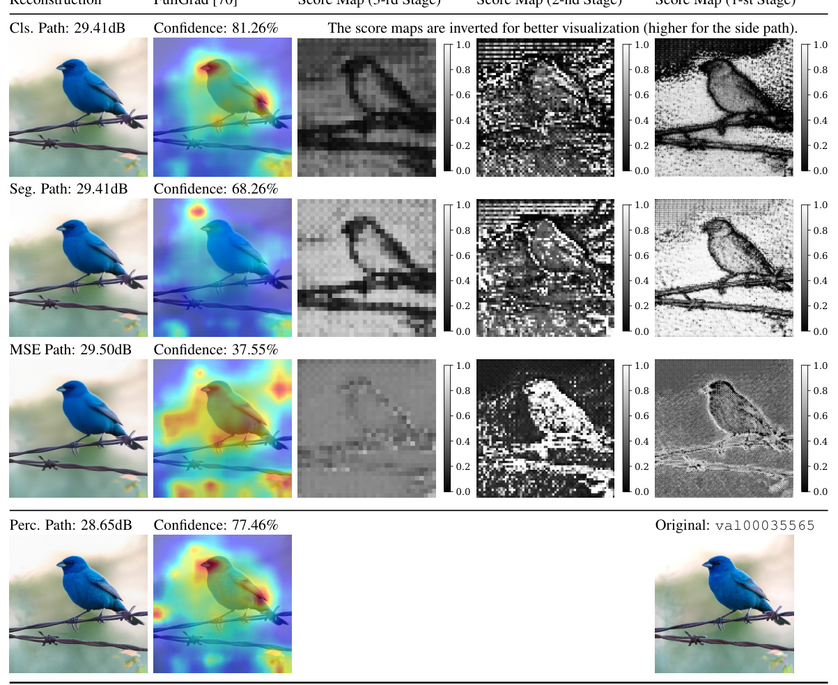
🔼 This figure visualizes the results of reconstructing an image using different paths in the proposed MPA model, comparing it to the FullGrad method. It shows the original image, reconstructions using multiple paths (classification, MSE, perceptual), and the corresponding score maps from the importance predictor at three different stages in the decoder. The score maps highlight which features were prioritized for each path and task, illustrating the selective feature aggregation strategy of MPA. The bitrate for the reconstruction is also given.
read the caption
Figure 4: Visualization of the reconstructed images, FullGrad [70] and score maps. The image is from ImageNet [14] and resized to 256×256×3. The regions with warmer colors in FullGrad have larger gradients, indicating a stronger impact on the classification decision. The bitrate is 0.0888bpp.
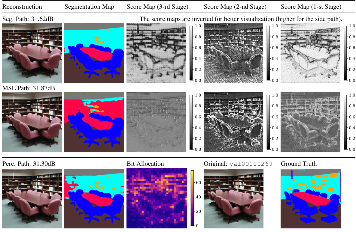
🔼 This figure shows the results of the proposed Multi-Path Aggregation (MPA) method on a semantic segmentation task. The top row shows the original image, the segmentation map (ground truth), and the score maps from three different stages of the decoder. The score maps are represented in grayscale; brighter pixels indicate the side path was prioritized. The bottom row shows the reconstructed images using the three different paths: MSE path (focuses on minimizing mean squared error), perceptual path (focuses on perceptual quality), and segmentation path (focuses on accurate segmentation). The bitrate is indicated for the reconstructed images. This illustrates the ability of MPA to perform well on multiple tasks with different objectives.
read the caption
Figure 5: Visualization of the reconstructed images, segmentation maps and score maps. The image is from ADE20K [83] and resized to 512×512×3. The bitrate is 0.0718bpp.
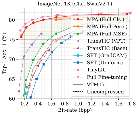
🔼 This figure presents a comparison of the multi-task performance of the proposed Multi-Path Aggregation (MPA) method against several state-of-the-art methods. The results are shown for various tasks involving image compression (Kodak and CLIC datasets, focusing on distortion and realism), classification (ImageNet-1K dataset), and segmentation (ADE20K dataset). The plots show the relationship between bitrate (bpp) and performance metrics (PSNR, LPIPS, Top-1 Accuracy, mIoU). The solid lines represent the performance of variable-rate models, while dashed lines represent single-rate models. The colored shaded regions illustrate the adjustable range achievable by the MPA model.
read the caption
Figure 3: Multi-task performance. The curves of variable-rate models are plotted as solid lines, while dashed lines are for single-rate models. Colored areas represent the adjustable range of MPA.
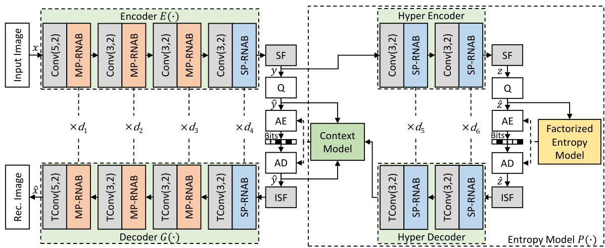
🔼 This figure shows the architecture of the Multi-Path Aggregation (MPA) integrated into the TinyLIC image coding framework. It illustrates the encoder and decoder components, highlighting the use of multiple RNAB (Residual Neighborhood Attention Block) blocks in each stage. The figure shows how the input image is encoded into latent representations (ŷ and ẑ), processed through a context model, and then decoded back into the reconstructed image. It also depicts the use of scaling factors (SF), arithmetic encoding (AE), and arithmetic decoding (AD) within the coding process. The hyper encoder and decoder are used to improve the model’s efficiency and performance. The diagram clearly illustrates the flow of data from the input image to the final reconstructed image and the various components that facilitate this process.
read the caption
Figure 7: MPA in TinyLIC [55]. di is the number of RNABs used at i-th stage. Convolution Conv(k,s) and its transposed version TConv(k,s) apply the kernel at a size of k × k and a stride of s. Uniform Quantization is used in Q; AE and AD stand for respective Arithmetic Encoding and Decoding.
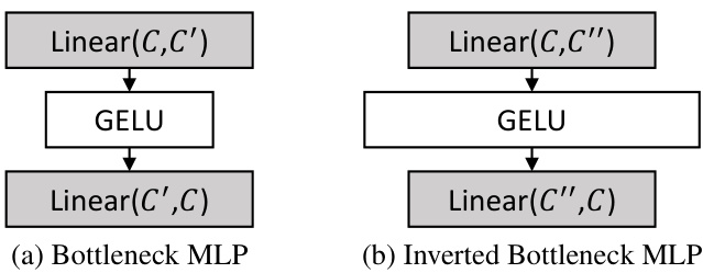
🔼 This figure shows the architecture of two types of Multi-Layer Perceptrons (MLPs) used in the Multi-Path Aggregation (MPA) module. The first is a bottleneck MLP, which reduces the number of channels before expanding them again, and the second is an inverted bottleneck MLP that expands the channels before reducing them. The choice of MLP type depends on the task and the desired complexity. Bottleneck MLPs are used for low bitrate coding for efficiency, while inverted bottleneck MLPs achieve higher realism for high bitrate coding.
read the caption
Figure 8: Two types of MLP. Linear(C, C') denotes a fully-connected layer with C input channels and C' output channels. We set C' = C/2 and C' = 2C in our implementation.
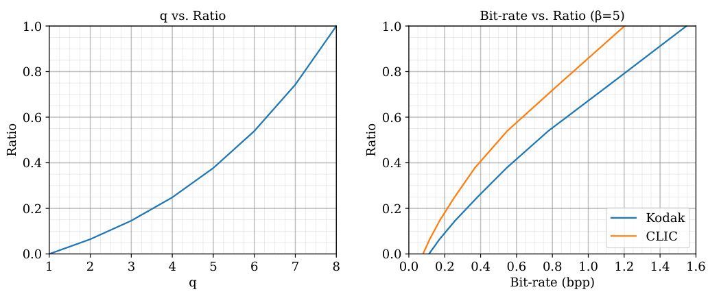
🔼 This figure shows two plots illustrating the relationship between two variables: q and the aggregation ratio penc. The left plot displays the relationship between q and the ratio. The right plot shows the relationship between the bitrate and the ratio for two different datasets: Kodak and CLIC. The plots are likely used to demonstrate how the parameter q, controlling the quality, affects the distribution of features between the main and side paths in the Multi-Path Aggregation (MPA) module of the image coding model. A higher q value leads to a higher proportion of features being assigned to the high-quality path. The different curves in the right plot suggest that this relationship may vary depending on the specific dataset used.
read the caption
Figure 9: The relationship between q and the aggregation ratio penc.
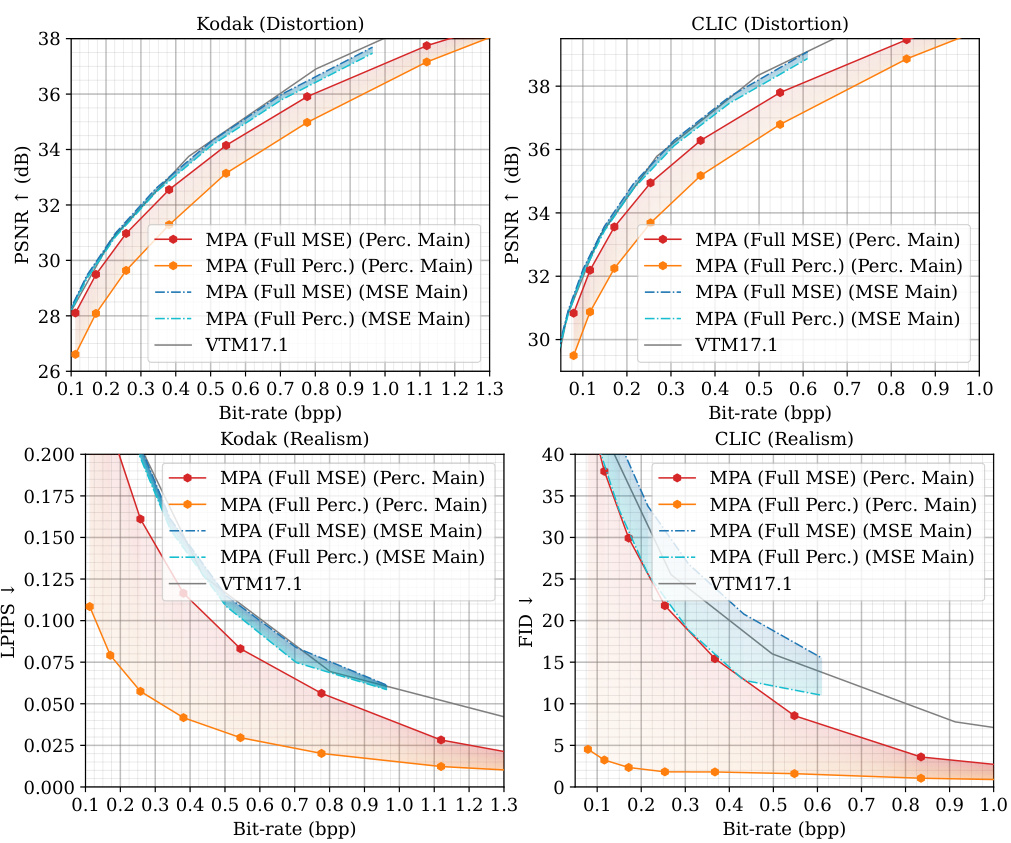
🔼 This figure presents the multi-task performance results comparing MPA against other state-of-the-art methods. It shows the rate-distortion (R-D) and rate-perception (R-P) performance for four tasks: Kodak distortion, Kodak realism, CLIC distortion, and CLIC realism. The curves for variable-rate models are in solid lines, while single-rate models are represented by dashed lines. The colored regions highlight the adjustable range offered by MPA, showcasing its flexibility in balancing performance across different tasks.
read the caption
Figure 3: Multi-task performance. The curves of variable-rate models are plotted as solid lines, while dashed lines are for single-rate models. Colored areas represent the adjustable range of MPA.
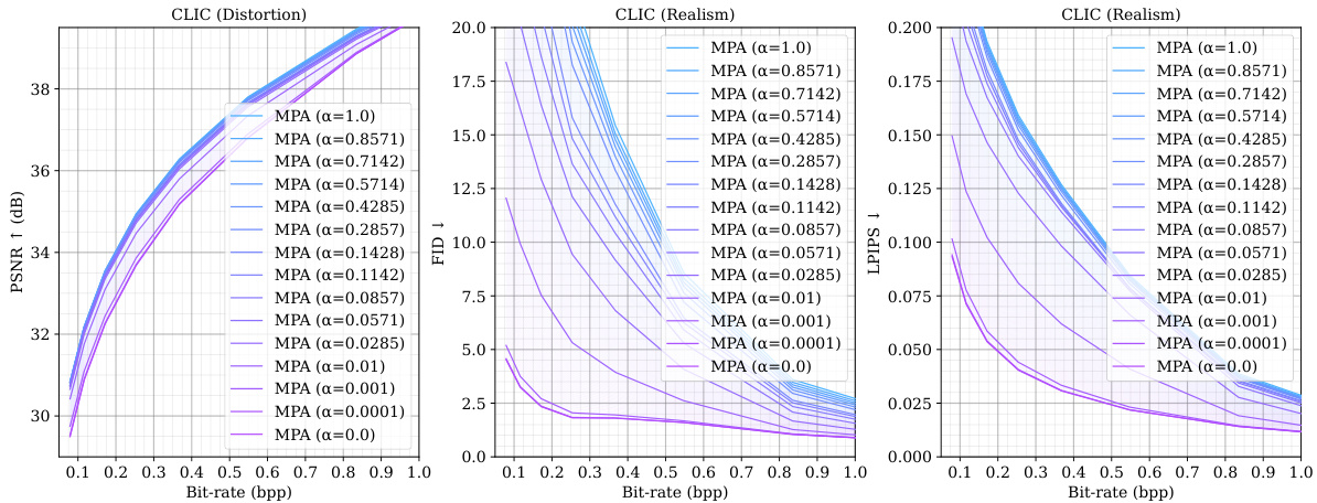
🔼 This figure presents the results of multi-task performance evaluation, comparing MPA against several state-of-the-art methods. It shows the rate-distortion (R-D) performance for various tasks (distortion, realism for human vision, classification accuracy, segmentation mIoU for machine vision). The solid lines represent variable-rate models, while dashed lines represent single-rate models. The colored areas highlight the range of performance that can be achieved by adjusting MPA’s parameters for seamless transitions between different tasks.
read the caption
Figure 3: Multi-task performance. The curves of variable-rate models are plotted as solid lines, while dashed lines are for single-rate models. Colored areas represent the adjustable range of MPA.
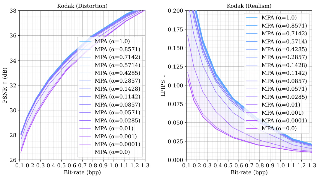
🔼 This figure presents the multi-task performance evaluation of the proposed Multi-Path Aggregation (MPA) method compared to state-of-the-art methods. The results are shown as Rate-Distortion (R-D) curves for multiple tasks. Solid lines represent the performance of variable-rate models using the MPA method, while dashed lines show the performance of single-rate models. The colored areas highlight the flexibility of MPA in adjusting the performance balance across multiple tasks. The tasks are human vision (perceptual quality and distortion) and machine vision (classification and segmentation). The different colors on the plots represent different tasks and methods. The plots demonstrate that MPA achieves competitive performance.
read the caption
Figure 3: Multi-task performance. The curves of variable-rate models are plotted as solid lines, while dashed lines are for single-rate models. Colored areas represent the adjustable range of MPA.
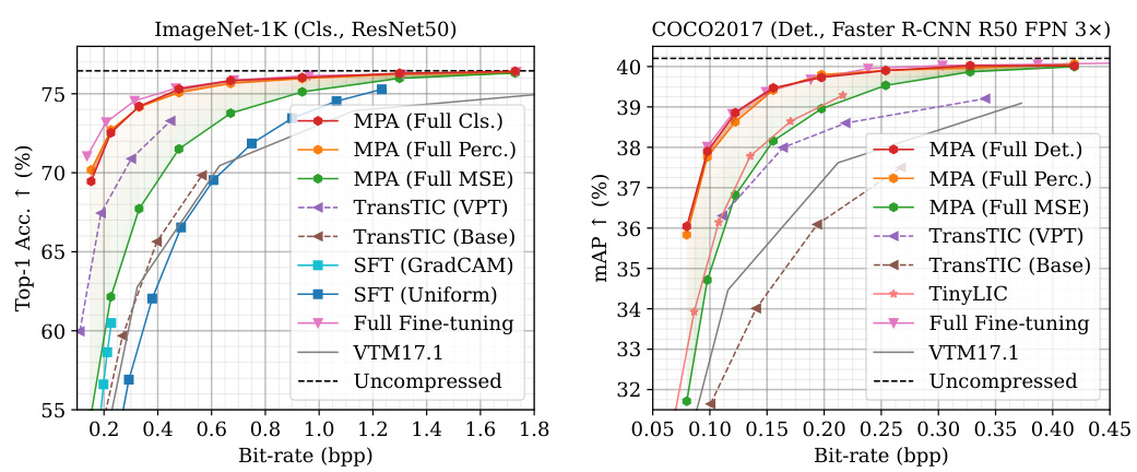
🔼 This figure presents a comparison of the multi-task performance of the proposed Multi-Path Aggregation (MPA) method against several state-of-the-art (SOTA) baselines for both human vision and machine vision tasks. The results are shown across four different metrics (distortion, realism, classification accuracy, and segmentation accuracy) plotted against bitrate. The solid lines represent the performance of variable-rate models, while the dashed lines represent single-rate models. The shaded areas highlight the adjustable performance range of the MPA method, indicating its flexibility across different tasks and bitrate requirements. The figure demonstrates MPA’s ability to achieve comparable performance to SOTA methods while offering more flexibility in task optimization and bitrate control.
read the caption
Figure 3: Multi-task performance. The curves of variable-rate models are plotted as solid lines, while dashed lines are for single-rate models. Colored areas represent the adjustable range of MPA.
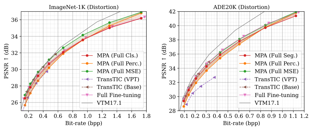
🔼 This figure presents the results of multi-task performance evaluation comparing the proposed MPA model against several state-of-the-art methods across different vision tasks and metrics. The plots illustrate the rate-distortion (R-D) and rate-perception (R-P) performance for both human vision (distortion and realism) and machine vision (classification and segmentation). The solid lines show the performance of variable-rate models, whereas the dashed lines represent single-rate models. The shaded regions highlight the flexibility MPA offers in adjusting performance through control parameters.
read the caption
Figure 3: Multi-task performance. The curves of variable-rate models are plotted as solid lines, while dashed lines are for single-rate models. Colored areas represent the adjustable range of MPA.
🔼 This figure showcases the multi-task performance of the proposed Multi-Path Aggregation (MPA) method. It compares MPA’s performance against several state-of-the-art (SOTA) methods across different tasks (distortion, realism, classification, segmentation) for both human vision and machine analysis. The plots show the relationship between bitrate (bpp) and quality metrics (PSNR, LPIPS, Accuracy, mIoU). Solid lines represent variable-rate models, and dashed lines represent single-rate models. Colored areas highlight the flexible performance range achievable by MPA through task control.
read the caption
Figure 3: Multi-task performance. The curves of variable-rate models are plotted as solid lines, while dashed lines are for single-rate models. Colored areas represent the adjustable range of MPA.
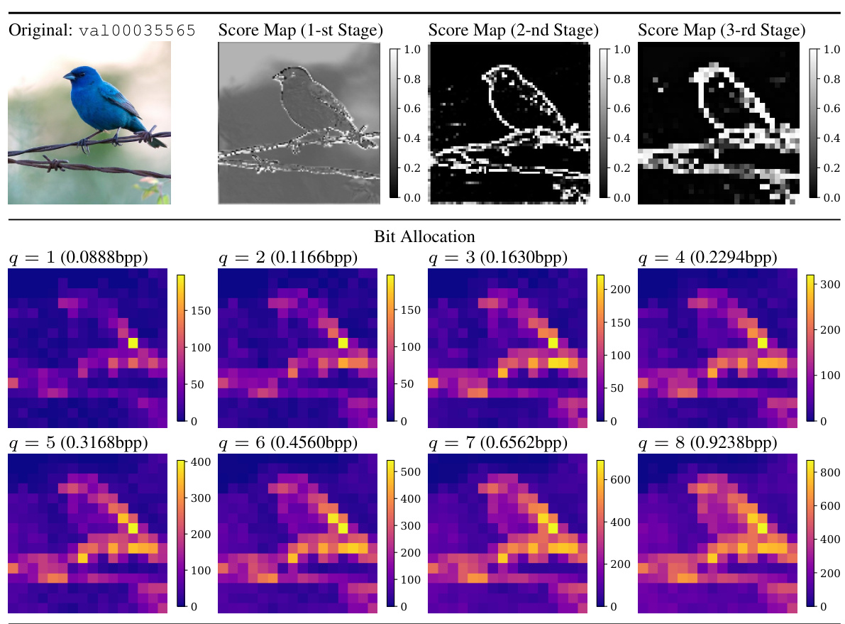
🔼 This figure visualizes how the proposed Multi-Path Aggregation (MPA) allocates features to different paths in the encoder at different bitrates. The bit allocation maps show the proportion of features assigned to each path (main path for generalized features, side paths for task-specific features) for eight different quality levels (q). The score maps illustrate the predictor’s output for the three encoder stages, providing insights into the feature allocation process at each level. This allows for a better understanding of the dynamic feature allocation strategy of MPA during the encoding process.
read the caption
Figure 16: We visualize the bit allocation and score maps in the encoder. The image is from ImageNet validation set [14] and resized to 256x256x3. The 1st, 2nd, and 3rd stages are the first three stages of the encoder, consecutively.
🔼 This figure visualizes the results of the proposed Multi-Path Aggregation (MPA) method on a single image from the ImageNet dataset. It compares the reconstructions from different paths within MPA (classification, MSE, perceptual) against the FullGrad method. The score maps show the feature allocation of each path across the encoder layers, illustrating how MPA distributes features based on task-specific importance and bitrate allocation. Warmer colors in the FullGrad visualizations indicate stronger influence on the classification decision, highlighting the differences in feature emphasis between different tasks and the methods.
read the caption
Figure 4: Visualization of the reconstructed images, FullGrad [70] and score maps. The image is from ImageNet [14] and resized to 256x256x3. The regions with warmer colors in FullGrad have larger gradients, indicating a stronger impact on the classification decision. The bitrate is 0.0888bpp.
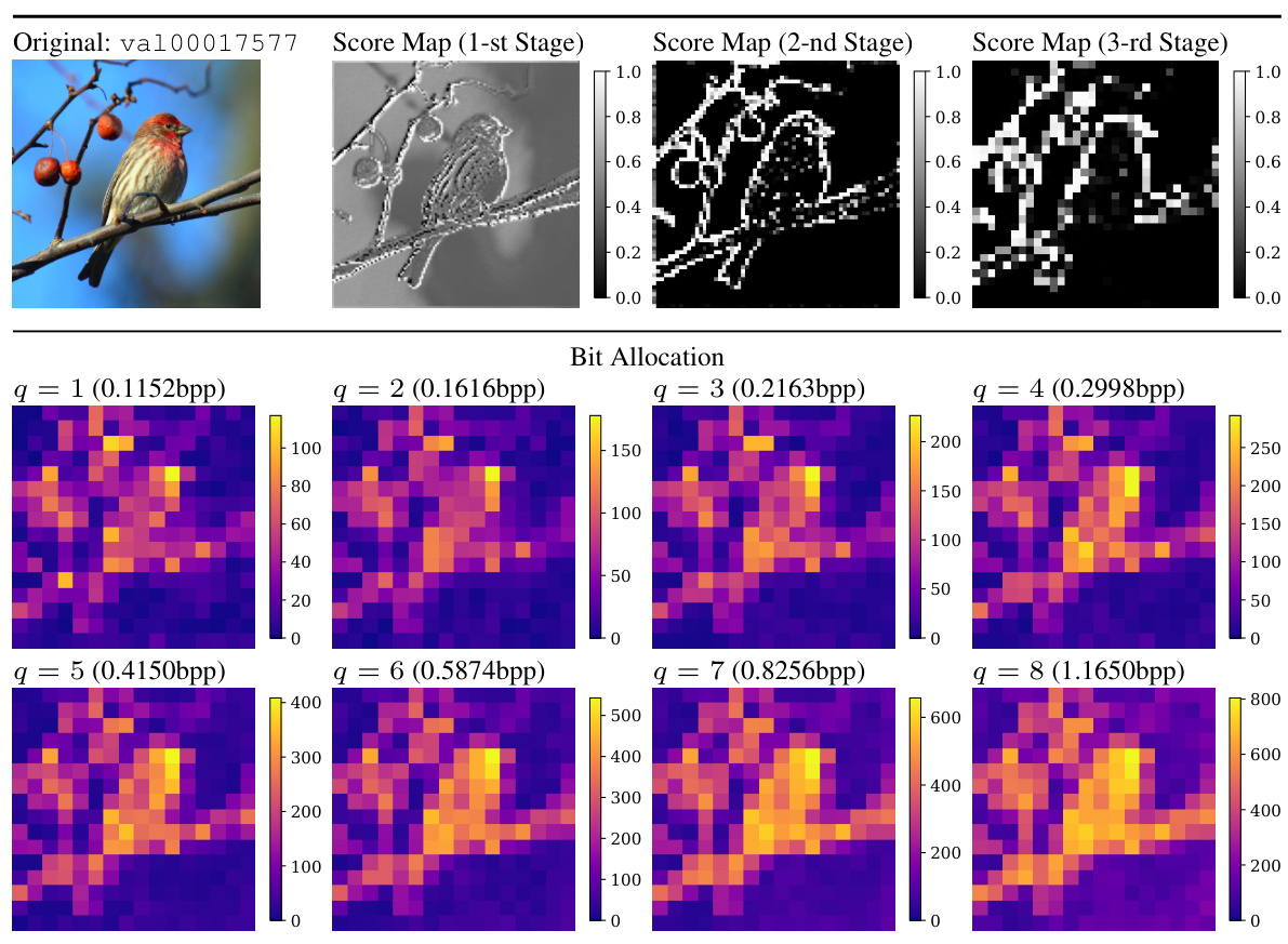
🔼 This figure visualizes how the model allocates features to different paths (main and side paths) in the encoder for various bitrates (controlled by the scaling factor q). It shows score maps for each stage of the encoder for different values of q. The score maps indicate the probability of each feature being allocated to the side path, which is specialized for certain tasks, while the main path is used for tasks that requires less customization. Higher values in the score maps indicate a higher probability of allocation to the side path.
read the caption
Figure 16: We visualize the bit allocation and score maps in the encoder. The image is from ImageNet validation set [14] and resized to 256×256×3. The 1st, 2nd, and 3rd stages are the first three stages of the encoder, consecutively.
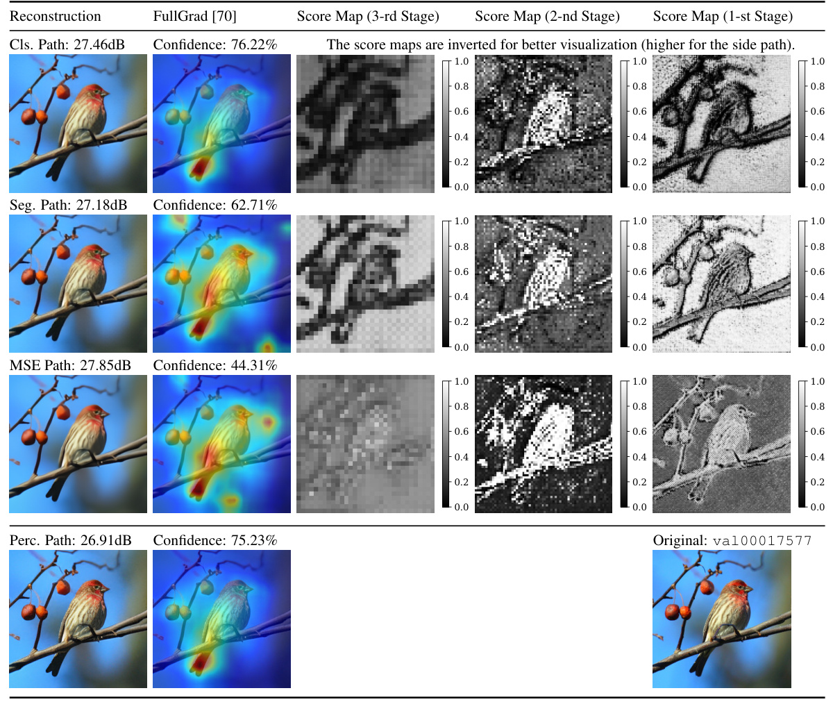
🔼 This figure visualizes the results of applying the Multi-Path Aggregation (MPA) method on an image from the ImageNet dataset. The figure shows the original image, the reconstructed images using different paths (classification, segmentation, MSE, and perceptual paths), and the score maps produced by the importance score predictor for each path and stage. The score maps illustrate feature allocation among different paths, showing how the model prioritizes features for each specific task at different stages. The bitrate and perceptual quality measures (FullGrad) are also shown for each path.
read the caption
Figure 17: We visualize the reconstructed images, FullGrad [70] and score maps predicted by importance predictors in each path. The image is from ImageNet validation set [14] and resized to 256x256x3. The 3rd, 2nd, and 1st stages are the last three stages of the decoder, consecutively. The regions with warmer colors in FullGrad represent areas with larger gradients, indicating a stronger impact on the classification decision. q is set to 1 for a more distinct comparison. Note that the score maps are inverted for better visualization, i.e., larger scores indicate prioritized for entering the selected side path. The bitrate is 0.0888bpp.
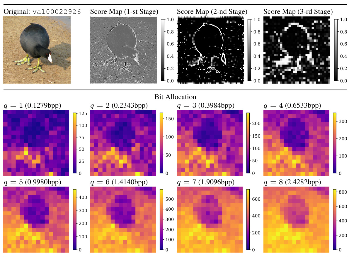
🔼 This figure visualizes how the bit allocation and feature importance scores change across different stages of the encoder for a specific image from the ImageNet validation set. The bit allocation shows how the total number of bits is distributed across different quality levels (q=1 to q=8). The score maps illustrate how a predictor within the Multi-Path Aggregation (MPA) module assigns feature importance to various paths for different tasks, visually showing how the model’s decision-making process changes during encoding.
read the caption
Figure 20: We visualize the bit allocation and score maps in the encoder. The image is from ImageNet validation set [14] and resized to 256x256x3. The 1st, 2nd, and 3rd stages are the first three stages of the encoder, consecutively.
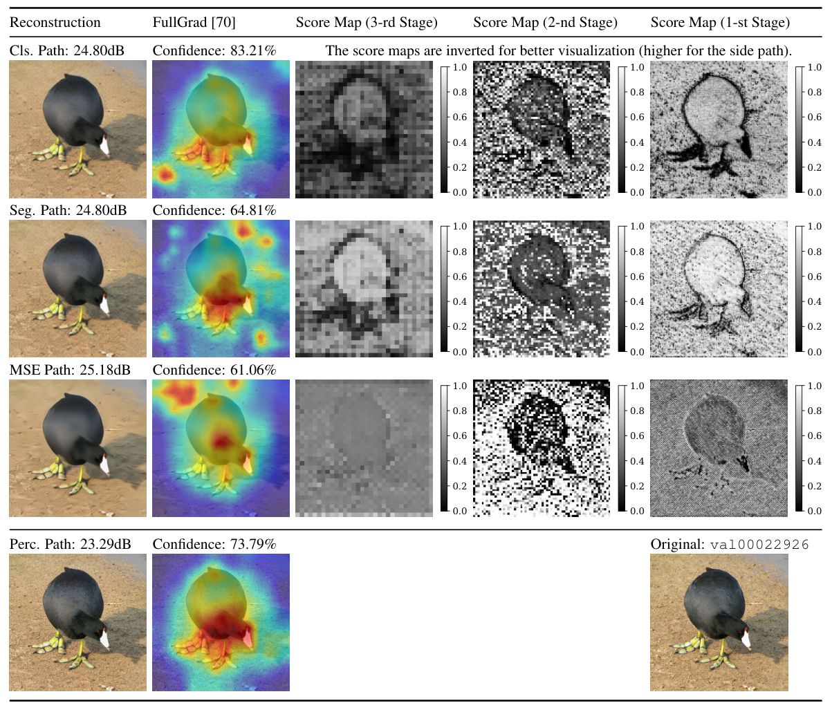
🔼 This figure visualizes the results of the proposed Multi-Path Aggregation (MPA) method on an image from the ImageNet validation set. It shows the reconstructed image from four different paths (classification, segmentation, MSE, and perceptual) within the decoder, alongside the corresponding FullGrad [70] visualizations. The score maps for each stage of the decoder are displayed, indicating which features were prioritized for each path by the importance score predictor. The overall bitrate used is 0.1279bpp.
read the caption
Figure 21: We visualize the reconstructed images, FullGrad [70] and score maps predicted by importance predictors in each path. The image is from ImageNet validation set [14] and resized to 256x256x3. The 3rd, 2nd, and 1st stages are the last three stages of the decoder, consecutively. q is set to 1 for a more distinct comparison. Note that the score maps are inverted for better visualization, i.e., larger scores indicate prioritized for entering the selected side path. The bitrate is 0.1279bpp.
🔼 This figure illustrates the architecture of the proposed Multi-Path Aggregation (MPA) method. It shows how MPA replaces the standard MLP layer in a typical Vision Transformer (ViT) block. The key components of MPA are highlighted: a predictor (P) to allocate features, a split operation (S) to divide features into main and side paths, and an aggregation operation (A) to combine the processed features from both paths. Layer normalization (LN) and scaling factors (SF) are also included. The figure clarifies the role of different elements in the MPA structure, showing its integration into a ViT block for multi-task image coding.
read the caption
Figure 2: The proposed Multi-Path Aggregation (MPA). Compared to typical Vision Transformer (ViT) block [73, 16], original MLP is replaced with MPA. LN and SF are Layer Normalization and Scaling Factors [10]. P, S and A denote predictor, split and aggregation respectively. C represents the number of input channels. p is the ratio penc in the encoder or the ratio pdec in the decoder.
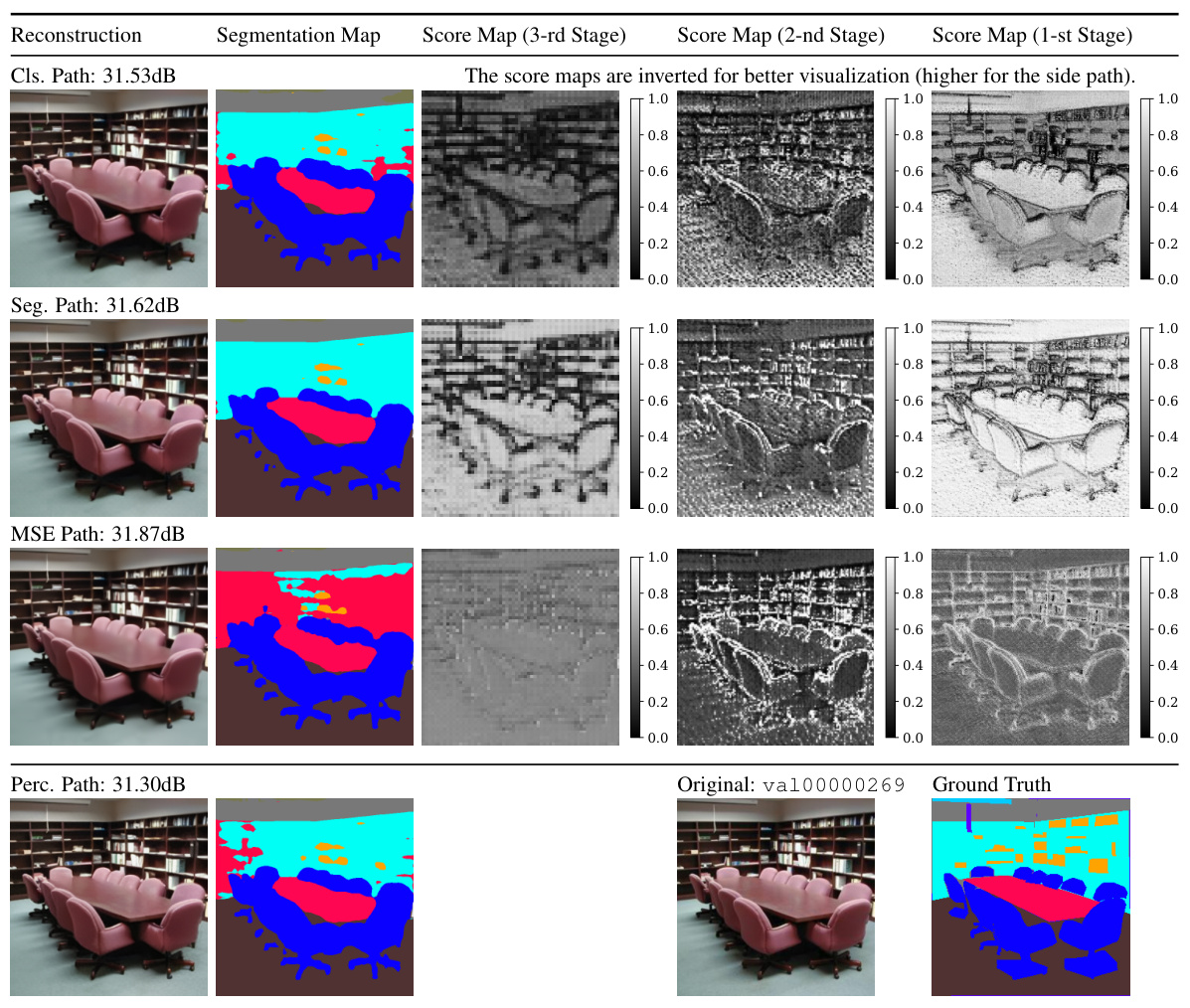
🔼 This figure shows the results of the proposed Multi-Path Aggregation (MPA) method on an image from the ADE20K dataset. It displays the reconstructed image, segmentation map, and score maps for each path (classification, segmentation, MSE, and perceptual). The score maps visualize the importance scores assigned by the predictor for feature allocation. Higher scores indicate features are more important for that path. The bitrate is 0.0718bpp, demonstrating efficient compression.
read the caption
Figure 27: We visualize the reconstructed images, segmentation map and score maps predicted by importance predictors in each path. The image is from ADE20K validation set [83] and resized to 512x512x3. The 3rd, 2nd, and 1st stages are the last three stages of the decoder, consecutively. q is set to 1 for a more distinct comparison. Note that the score maps are inverted for better visualization, i.e., larger scores indicate prioritized for entering the selected side path. The bitrate is 0.0718bpp.
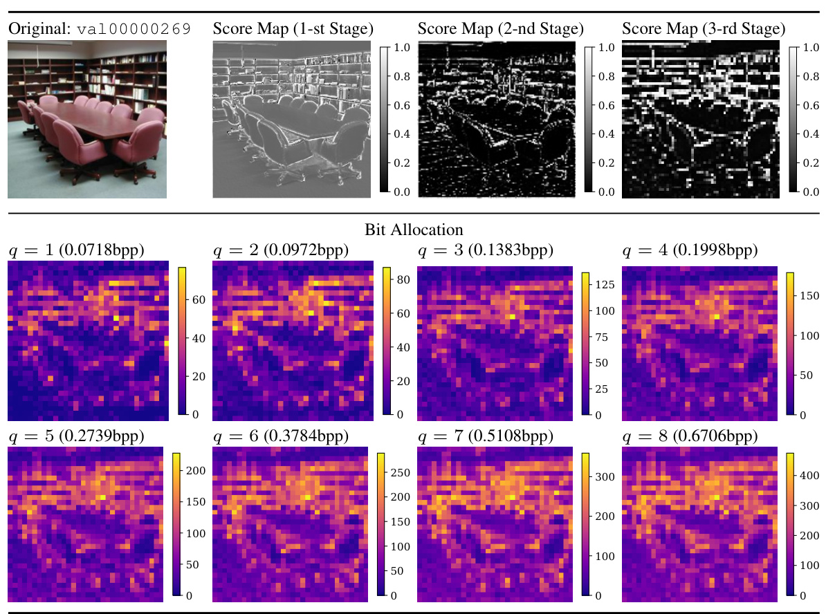
🔼 This figure visualizes the bit allocation and score maps generated by the importance score predictor in the encoder. The input image is from the ADE20K validation set, resized to 512x512x3. The three stages shown represent the first three stages of the encoder. Each subplot displays a score map for a different stage, and the color intensity represents the score value (higher values indicate a higher priority for allocation to a specific path). The figure also shows the bit allocation as a function of the quality factor (q).
read the caption
Figure 24: We visualize the bit allocation and score maps in the encoder. The image is from ADE20K validation set [83] and resized to 512x512x3. The 1st, 2nd, and 3rd stages are the first three stages of the encoder, consecutively.
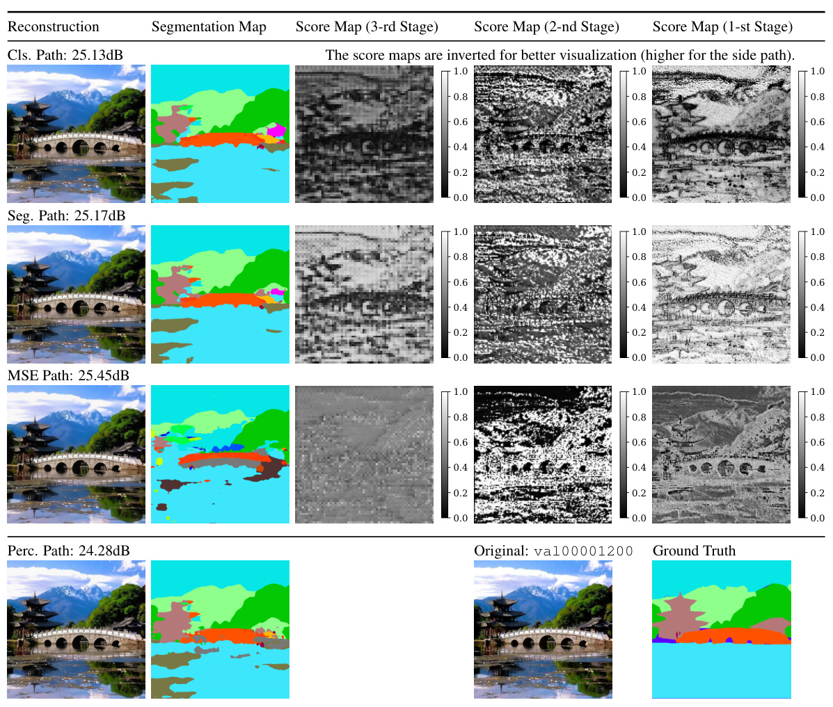
🔼 This figure visualizes the results of the Multi-Path Aggregation (MPA) method on an image from the ADE20K dataset. It compares the reconstruction quality for different tasks (classification, segmentation, MSE, perceptual) and shows the score maps generated by the importance score predictor at different decoder stages. The score maps illustrate how features are allocated to different paths based on their importance for each task.
read the caption
Figure 25: We visualize the reconstructed images, segmentation map and score maps predicted by importance predictors in each path. The image is from ADE20K validation set [83] and resized to 512×512×3. The 3rd, 2nd, and 1st stages are the last three stages of the decoder, consecutively. q is set to 1 for a more distinct comparison. Note that the score maps are inverted for better visualization, i.e., larger scores indicate prioritized for entering the selected side path. The bitrate is 0.1806bpp.
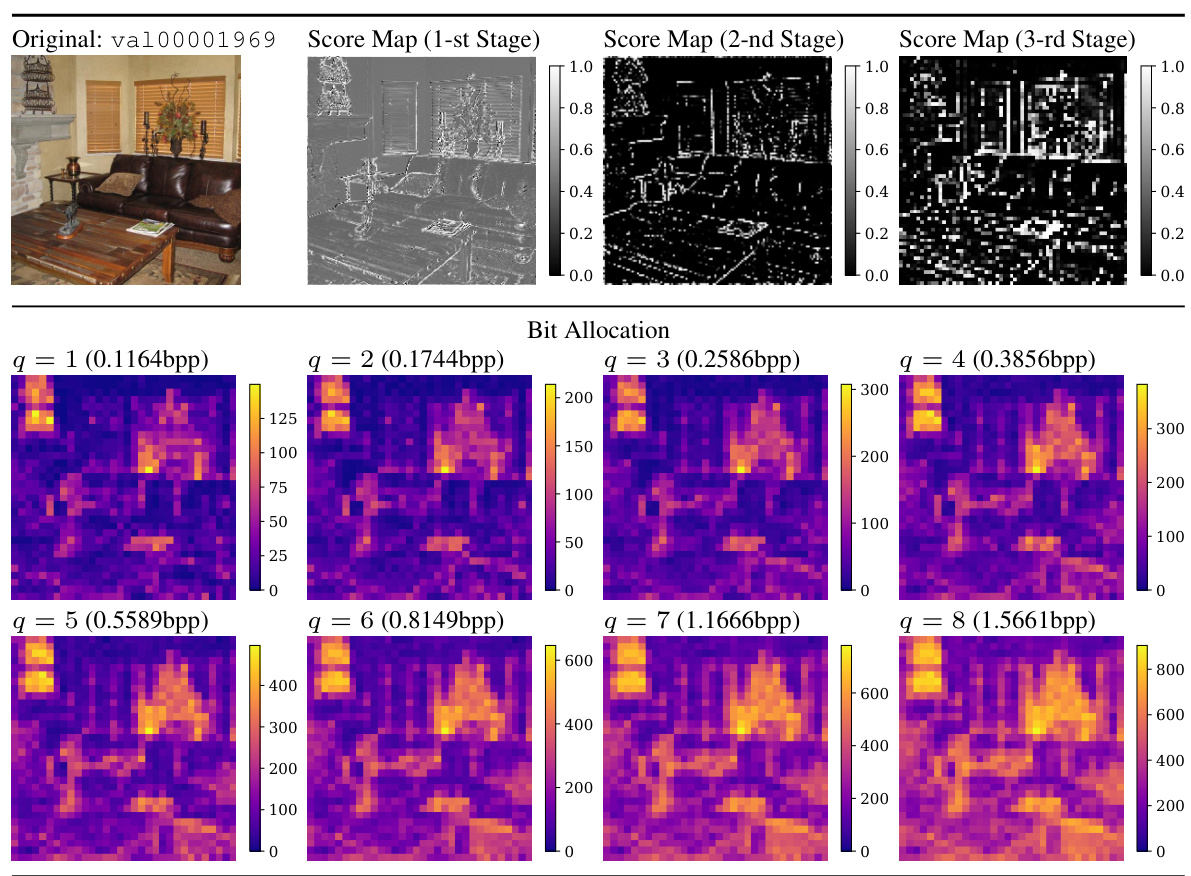
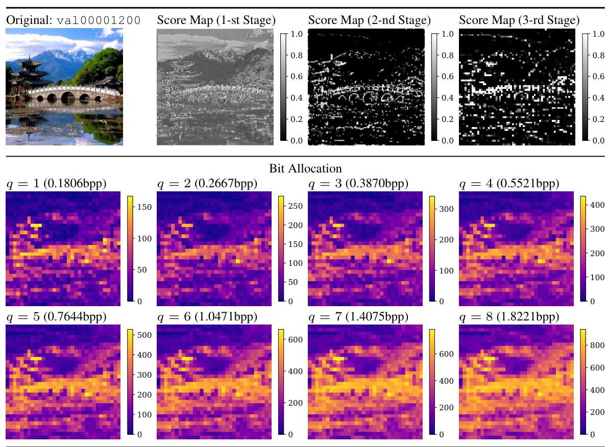
🔼 This figure visualizes how the bit allocation and feature importance scores change across the three stages of the encoder. The top row displays the original image, the first three stages’ score maps, and the final bit allocation. The bottom row shows the same visualization but with a more detailed bit allocation map for each of the eight quantization levels (q). Warmer colors indicate that the feature is prioritized to enter the side path.
read the caption
Figure 26: We visualize the bit allocation and score maps in the encoder. The image is from ADE20K validation set [83] and resized to 512×512×3. The 1st, 2nd, and 3rd stages are the first three stages of the encoder, consecutively.
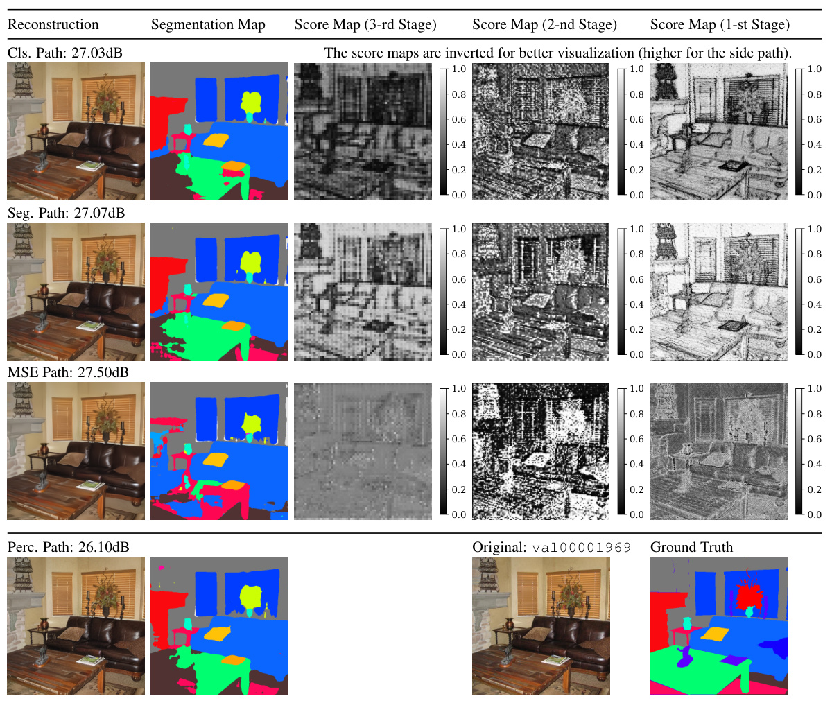
🔼 This figure visualizes the results of applying the Multi-Path Aggregation (MPA) method to an image from the ADE20K dataset. It shows the reconstructed image using different paths (classification, segmentation, MSE, perceptual) and the corresponding segmentation maps and score maps. The score maps illustrate how features are allocated to different paths by the model, based on their importance for each task. The bitrate used is 0.1164bpp and q is set to 1 for clarity.
read the caption
Figure 27: We visualize the reconstructed images, segmentation map and score maps predicted by importance predictors in each path. The image is from ADE20K validation set [83] and resized to 512×512×3. The 3rd, 2nd, and 1st stages are the last three stages of the decoder, consecutively. q is set to 1 for a more distinct comparison. Note that the score maps are inverted for better visualization, i.e., larger scores indicate prioritized for entering the selected side path. The bitrate is 0.1164bpp.
More on tables

🔼 This table presents the results of an ablation study conducted to evaluate the impact of different Multi-Layer Perceptron (MLP) architectures on the overall performance of the proposed Multi-Path Aggregation (MPA) method. Specifically, it compares the performance of using bottleneck MLPs versus inverted bottleneck MLPs for the MSE, classification (Cls), and segmentation (Seg) tasks. The metrics used for evaluation include BD-Rate (lower is better), accuracy (higher is better), and mIoU (higher is better).
read the caption
Table 1: Effects of path complexity

🔼 This table presents the results of cross-validation experiments conducted to evaluate the performance of different path choices in the Multi-Path Aggregation (MPA) model. The table shows the performance metrics (BD-Rate, Accuracy, and mIoU) for the MSE, Classification, and Segmentation tasks when using different combinations of paths, such as the perceptual path (perc), MSE path (MSE), classification path (cls), and segmentation path (seg). It demonstrates how the selection of paths affects the overall performance of the model for each task. The lowest BD-Rate values are in bold.
read the caption
Table 2: Cross-validations on path choices

🔼 This table compares the model complexity (number of parameters, KFLOPs per pixel, and latency) of the proposed Multi-Path Aggregation (MPA) method with other methods such as MRIC and TinyLIC. It shows the impact of adding different components to the MPA architecture on its computational cost.
read the caption
Table 4: Comparison of complexity
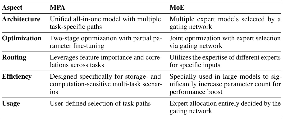
🔼 This table compares the proposed Multi-Path Aggregation (MPA) method with the Mixture-of-Experts (MoE) approach in terms of architecture, optimization strategy, feature routing, efficiency, and usage. MPA uses a unified all-in-one model with task-specific paths, employing a two-stage optimization process that fine-tunes only a small portion of the parameters. It leverages feature importance and correlations to efficiently allocate resources across different tasks, making it suitable for resource-constrained multi-task scenarios. In contrast, MoE uses multiple expert models selected by a gating network, requiring joint optimization and potentially leading to a large number of parameters. Expert allocation is fully determined by the gating network, unlike MPA’s user-defined task path selection.
read the caption
Table 5: Comparison between MPA and MoE

🔼 This table compares the rate-distortion performance of the proposed Multi-Path Aggregation (MPA) method with the Low-Rank Adaptation (LoRA) method. It shows the BD-rate reduction achieved by each method against the Versatile Video Coding (VTM) baseline on the Kodak and CLIC datasets. Different rank values for LoRA are tested to explore the impact of model complexity on performance. The MSE path is optimized for low distortion in both methods.
read the caption
Table 6: R-D performance comparison between MPA and LoRA. The ranks r of LoRA are set to 64, 16, and 4, respectively, and the lora_alpha (NOT the a in MPA) is fixed to 1. We optimize MSE paths for low distortion. Other experimental settings are consistent with those in Sec. 4.

🔼 This table presents the ablation study on the loss terms used for training the classification path in the proposed MPA model. It shows the impact of each loss term (MSE, perceptual, and cross-entropy) on various metrics, including PSNR, LPIPS, and top-1 accuracy on two different datasets (ConvNeXt-T and SwinV2-T). The results are evaluated at a specific bitrate (0.1521bpp) and the top-3 performing combinations are highlighted.
read the caption
Table 7: Ablations on loss terms in Ltask. We use the same experimental settings as in Sec. 4, and re-train the classification path for each case. Metrics are evaluated at 0.1521bpp on ImageNet-1K [14]. The top-3 results are underlined. LMSE, Lperc and Lce denote MSE loss, perceptual loss and cross-entropy loss respectively.
🔼 This table compares Multi-Path Aggregation (MPA) and Mixture-of-Experts (MoE) approaches across several key aspects. It highlights the differences in architecture (unified vs. multiple expert models), optimization strategies (two-stage partial vs. joint optimization), routing mechanisms (leveraging feature importance and correlations vs. gating networks), efficiency (designed for storage-sensitive scenarios vs. large parameter models), and usage (user-defined vs. automatic allocation). The table clarifies how MPA, designed for storage-efficient multi-task coding, contrasts with the more resource-intensive MoE approach.
read the caption
Table 5: Comparison between MPA and MoE
Full paper#


