TL;DR#
Accurate 3D object detection is crucial for autonomous vehicles. While existing radar-camera fusion methods improve detection, they often struggle with dynamic objects due to a lack of effective temporal information integration. This leads to limited performance in real-world scenarios, where objects are constantly moving.
CRT-Fusion is a new framework that tackles this problem by directly integrating temporal information from both camera and radar sensors. This is achieved via three key modules: Multi-View Fusion (MVF), Motion Feature Estimator (MFE), and Motion Guided Temporal Fusion (MGTF). The results show that CRT-Fusion outperforms existing methods, demonstrating a significant improvement in accuracy and robustness by successfully capturing and compensating for object motion. This makes 3D object detection more reliable and applicable in real-world scenarios.
Key Takeaways#
Why does it matter?#
This paper is significant because it presents CRT-Fusion, a novel framework that substantially improves 3D object detection accuracy and robustness by effectively integrating temporal information into radar-camera fusion. This addresses a critical challenge in autonomous vehicles and robotics, paving the way for safer and more reliable systems. Its state-of-the-art performance on the challenging nuScenes dataset highlights the impact, and its modular design offers avenues for future improvements and adaptations.
Visual Insights#

🔼 This figure compares different approaches to temporal fusion in 3D object detection. (a) shows how previous methods simply concatenate BEV (bird’s-eye view) feature maps from different time frames without accounting for object motion. (b) illustrates the CRT-Fusion approach, which estimates and compensates for object motion before concatenation, leading to a more accurate representation. (c) presents a bar graph demonstrating the performance improvement of CRT-Fusion over the direct concatenation method, showing gains across various object velocity ranges.
read the caption
Figure 1: Comparison of temporal fusion methods: (a) Previous methods concatenate BEV feature maps without considering object motion. (b) CRT-Fusion estimates and compensates for object motion before concatenation. (c) Performance gain of CRT-Fusion over the direct concatenation method, showing CRT-Fusion's superior accuracy across different object velocity ranges.
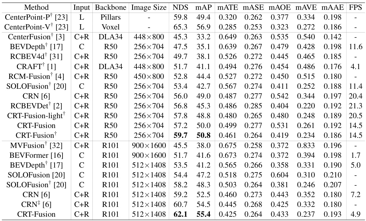
🔼 This table presents a comparison of the performance of different 3D object detection methods on the nuScenes validation set. The methods are categorized by the sensor types they use (LiDAR only, camera only, camera-radar fusion). Key performance metrics are reported, including NDS (NuScenes Detection Score), mAP (mean Average Precision), and various metrics related to accuracy of bounding box estimations (mATE, mASE, MAOE, mAVE, mAAE). The table also notes whether certain methods were trained using CBGS (Class-Balanced Grouping and Sampling) or TTA (Test Time Augmentation).
read the caption
Table 1: Performance comparisons with 3D object detector on the nuScenes val set. 'L', 'C', and 'R' represent LiDAR, camera, and radar, respectively. †: trained with CBGS. ‡: use TTA.
In-depth insights#
Motion-Aware Fusion#
Motion-aware fusion, in the context of 3D object detection, signifies a paradigm shift from traditional sensor fusion methods. Instead of simply concatenating data from different sensors (like cameras and radar) and time steps, a motion-aware approach explicitly models and compensates for the movement of objects. This is crucial because objects in motion appear differently across different sensor modalities and time frames. A key advantage is improved robustness to occlusions and sensor noise, as the system can predict object locations across various time instances, even when momentarily obscured. Accurate velocity estimation is paramount for effective motion compensation. The method also enables the generation of consistent and temporally coherent bird’s-eye-view representations, vital for downstream tasks like object tracking and trajectory prediction. A recurrent fusion mechanism further enhances temporal consistency, aligning and fusing feature maps across multiple timestamps. The overall impact is a significant enhancement in both the accuracy and robustness of 3D object detection, especially when dealing with dynamic objects and challenging real-world scenarios. However, the increased computational complexity and reliance on accurate velocity estimation are important limitations to consider.
Multi-View Fusion#
Multi-view fusion, in the context of 3D object detection, is a crucial technique aiming to leverage information from diverse sensor modalities. By combining data from multiple viewpoints, it enhances the robustness and accuracy of object detection. This approach is particularly beneficial in addressing challenges posed by limitations of individual sensors, such as occlusion or depth ambiguity. A core strength of multi-view fusion lies in its ability to create a more comprehensive scene representation than would be possible using a single sensor. Effective multi-view fusion strategies require careful consideration of data registration, feature extraction, and fusion methods. Techniques such as perspective and bird’s-eye view fusion are commonly used to integrate data from different viewpoints. The specific implementation choices depend on factors such as sensor characteristics and computational resources. A successful multi-view fusion method not only integrates information from different sensors but also addresses challenges such as sensor noise and data inconsistency. Therefore, multi-view fusion is vital in advancing the capabilities of autonomous systems and robotics.
Temporal Fusion#
The concept of ‘Temporal Fusion’ in the context of 3D object detection involves leveraging information from multiple timestamps to enhance the accuracy and robustness of object detection. This is crucial because single-frame sensor data (camera, radar, LiDAR) often suffers from limitations like occlusions or sensor noise. Temporal fusion aims to mitigate these limitations by integrating historical information, providing a more comprehensive understanding of object motion and environment dynamics. Different approaches exist, including fusing features across multiple frames or integrating temporal cues at the object-level. The effectiveness of temporal fusion heavily depends on how effectively object motion is estimated and compensated for. Motion prediction is crucial to ensure accurate alignment and fusion of features from different timestamps. Furthermore, a key challenge lies in efficiently processing the increased computational load that comes with incorporating temporal information. While effective, finding an efficient and effective architecture is important due to the tradeoff between performance gains and processing requirements.
NuScenes Dataset#
The research leverages the NuScenes dataset, a large-scale, multi-modal dataset for autonomous driving, to evaluate its proposed method. NuScenes provides a comprehensive benchmark with diverse scenes, rich annotations (including 3D bounding boxes and object attributes), and synchronized data from various sensor modalities (cameras, lidar, radar). This rich data is crucial for rigorously testing the algorithm’s performance in complex real-world scenarios, enabling a robust and fair comparison against state-of-the-art methods. The utilization of NuScenes underscores the research’s commitment to evaluating its algorithm’s practicality and generalizability in autonomous driving applications. The dataset’s diverse and challenging conditions make it a particularly valuable resource for testing algorithms capable of robust 3D object detection.
Future Works#
The paper’s ‘Future Works’ section would ideally delve into several crucial areas. Improving computational efficiency is paramount, given the resource intensiveness of temporal fusion, especially with increasing numbers of past frames considered. Exploring alternative architectures, such as recurrent neural networks, to replace the current parallel approach could drastically reduce computational burden. Further investigation of the method’s robustness across diverse weather and lighting conditions is vital for practical applications. The current evaluation demonstrates promising results but requires more extensive real-world testing under diverse conditions. Expanding the range of supported sensors beyond radar and camera could greatly enhance the system’s robustness. LiDAR integration, for example, would provide complementary depth information, mitigating some of the current limitations. Finally, rigorous analysis of the model’s fairness and potential biases is critical before deployment. This involves examining its performance across diverse datasets that represent various demographics and environmental factors to identify and mitigate any potential disparities.
More visual insights#
More on figures
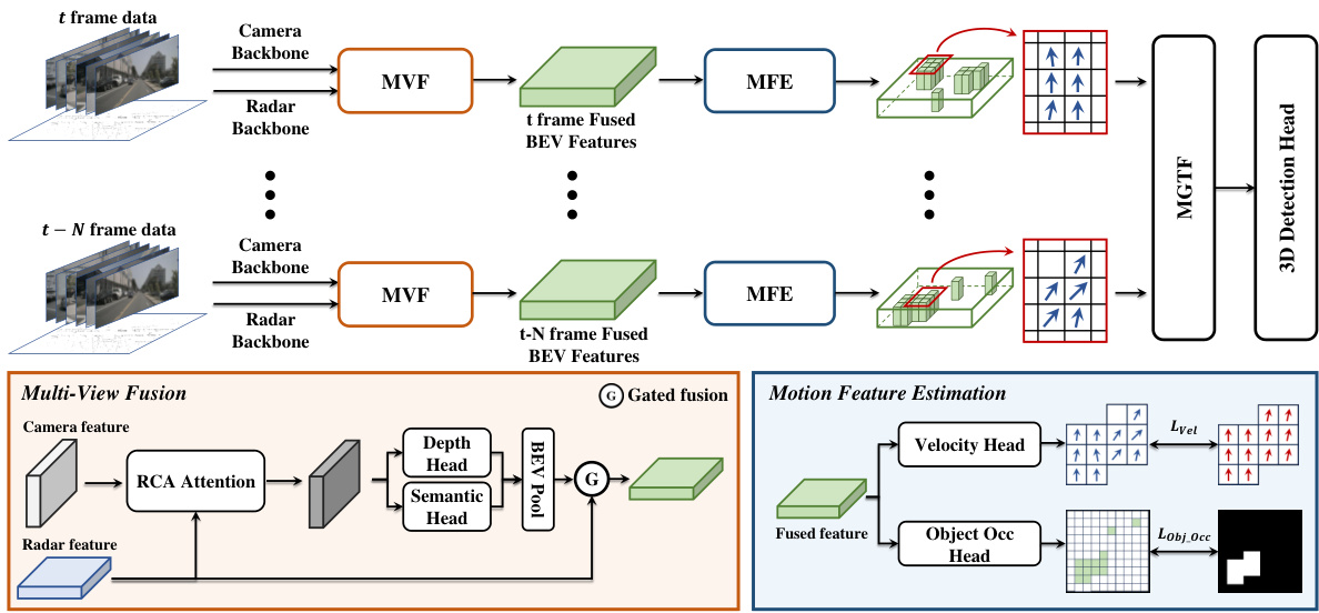
🔼 This figure illustrates the overall architecture of the CRT-Fusion framework for 3D object detection. It shows the flow of data from the input (camera and radar data at multiple timestamps) through different modules: Multi-View Fusion (MVF), Motion Feature Estimation (MFE), and Motion Guided Temporal Fusion (MGTF), finally leading to the 3D detection head that outputs the 3D object detection results. The MVF module fuses camera and radar features to create a unified BEV representation. The MFE module predicts object locations and velocities. The MGTF module aligns and fuses feature maps across multiple timestamps using the motion information from MFE. The detailed workings of MVF and MFE are shown as sub-figures.
read the caption
Figure 2: Overall architecture of CRT-Fusion: Features are extracted from radar and camera data using backbone networks at each timestamp. The MVF module combines these features to generate fused BEV feature maps. The MFE module predicts the location and velocity of dynamic objects from these maps. The MGTF module then uses the predicted motion information to create the final feature map for the current timestamp, which is fed into the 3D detection head.

🔼 This figure illustrates the core components of the CRT-Fusion framework. (a) shows the Radar-Camera Azimuth Attention (RCA) module, which enhances camera features with radar features to improve depth prediction accuracy. (b) shows the Motion Guided Temporal Fusion (MGTF) module, which compensates for object motion across multiple frames to generate a robust and temporally consistent bird’s-eye view (BEV) feature map. This refined BEV feature map is then used for 3D object detection.
read the caption
Figure 3: Core components of CRT-Fusion: (a) RCA module enhances image features with radar features for accurate depth prediction. (b) MGTF module compensates for object motion across multiple frames, producing the final BEV feature map for 3D object detection.
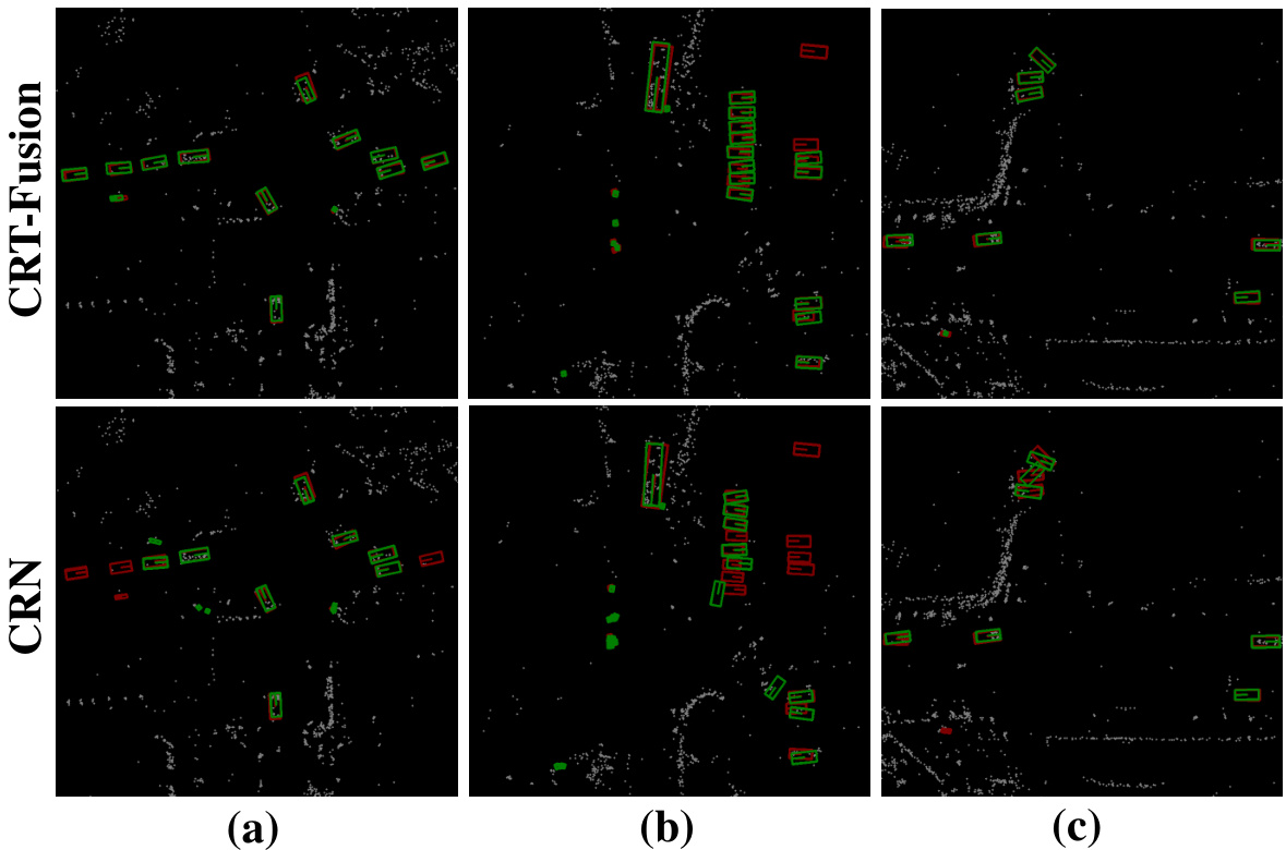
🔼 This figure presents a qualitative comparison of the 3D object detection results obtained using CRT-Fusion and CRN on the nuScenes validation set. Each image shows a BEV (bird’s-eye view) representation of a scene. Green boxes represent the bounding boxes predicted by CRT-Fusion, blue boxes show the bounding boxes predicted by CRN, and red boxes represent the ground truth annotations. The figure demonstrates that CRT-Fusion often produces more accurate and robust bounding boxes, particularly in challenging scenarios.
read the caption
Figure 4: Qualitative results comparing CRT-Fusion and CRN: Green boxes indicate CRT-Fusion prediction boxes, blue boxes denote CRN prediction boxes, and red boxes represent ground truth (GT) boxes.

🔼 This figure compares velocity prediction results between BEVDepth and CRT-Fusion using the Motion Feature Estimation (MFE) module. Ground truth boxes and velocities are shown in red. CRT-Fusion’s predictions are shown in white, with yellow highlighting areas of improved accuracy and orange highlighting areas where CRT-Fusion correctly identifies static objects that BEVDepth misclassifies as dynamic.
read the caption
Figure 5: Comparison of velocity prediction using the MFE module in BEVDepth and CRT-Fusion. Red boxes are the Ground Truth (GT) boxes, red arrows show GT velocity, and white arrows represent predicted velocity. Yellow highlights indicate areas where CRT-Fusion predicts velocity more accurately, while orange highlights show static objects correctly identified by CRT-Fusion but misclassified by BEVDepth.
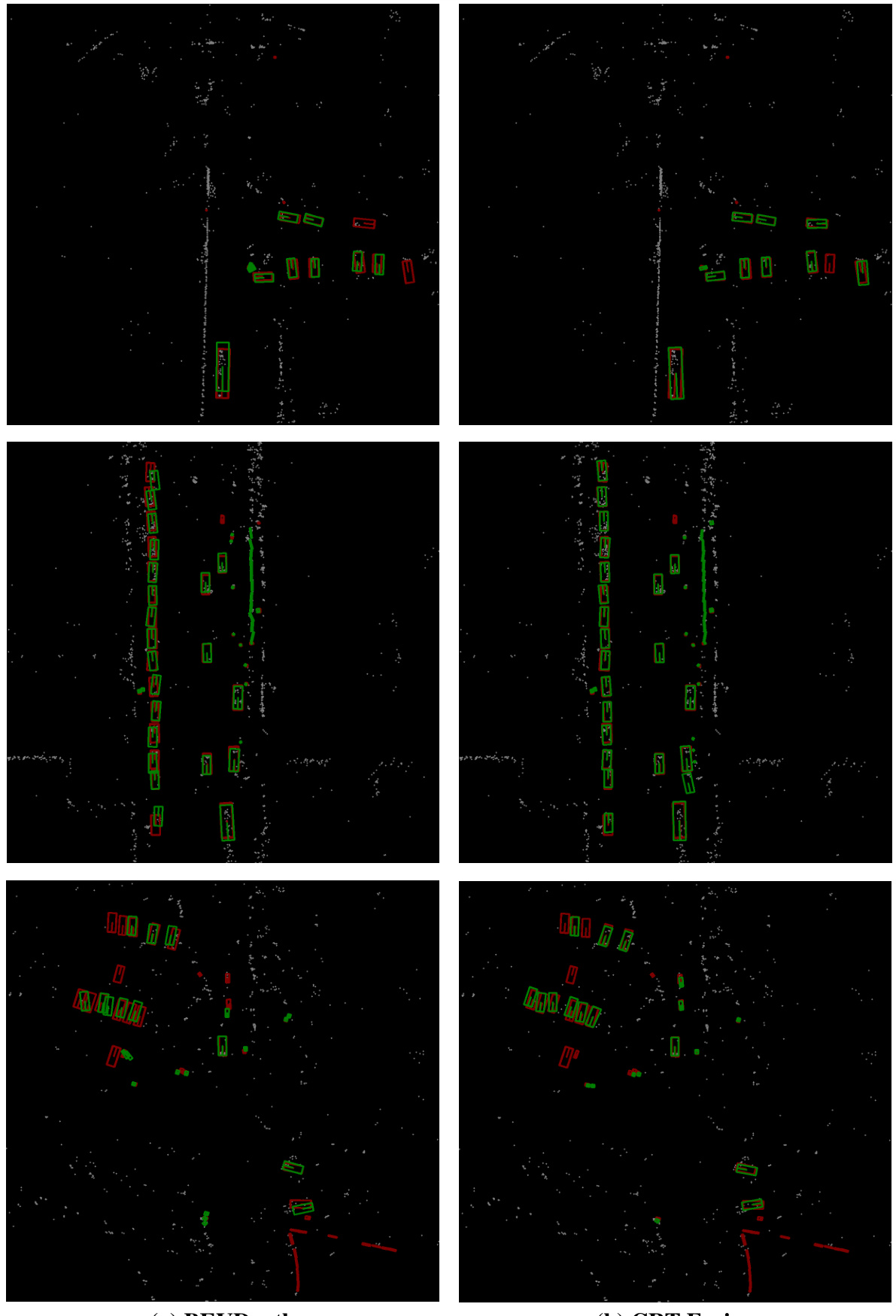
🔼 This figure compares the qualitative results of object detection between BEVDepth (baseline) and CRT-Fusion under various scenarios from the nuScenes validation set. For each scenario, three images are shown, from left to right: the BEVDepth prediction, the CRT-Fusion prediction, and the ground truth. Red boxes represent the ground truth bounding boxes, blue boxes indicate BEVDepth’s predictions, and green boxes show CRT-Fusion’s predictions. White points represent the radar point cloud data, which is used in the fusion process.
read the caption
Figure 6: Qualitative results under different scenarios on the nuScenes validation set. Red boxes represent ground truth annotations, while blue and green boxes indicate the predicted bounding boxes from BEVDepth and CRT-Fusion, respectively. The white points represent the radar point cloud.
More on tables
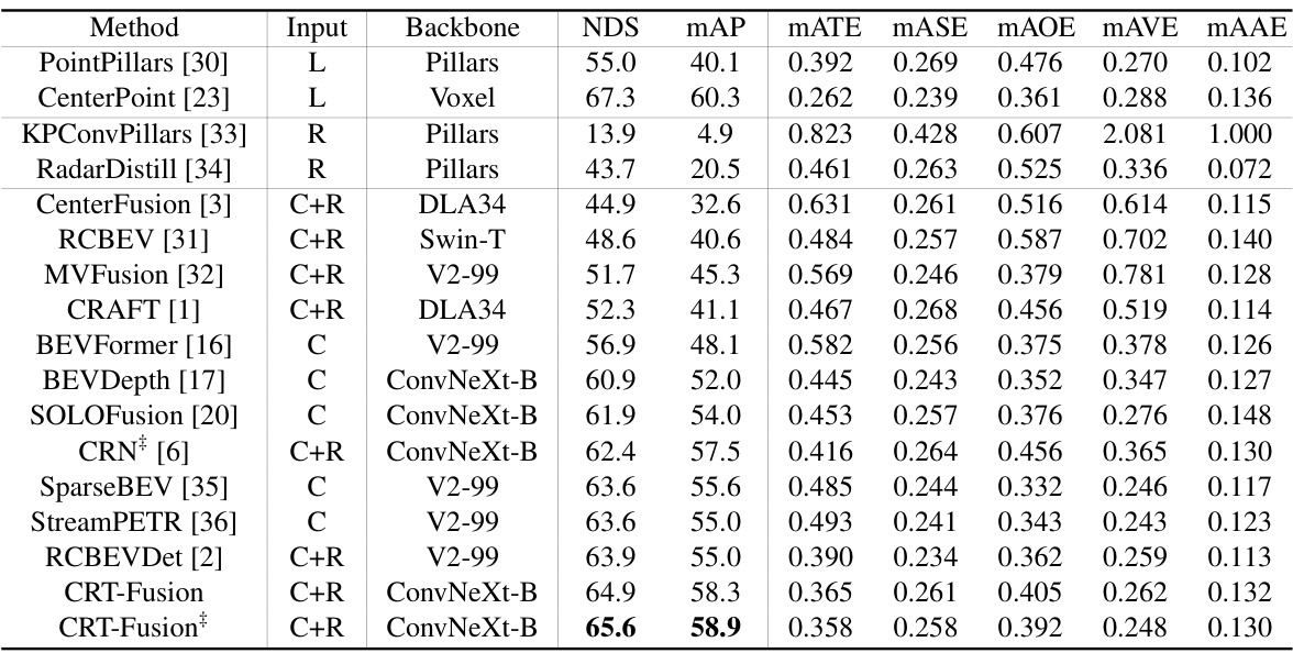
🔼 This table compares the performance of different methods for 3D object detection on the nuScenes validation set. The methods use various combinations of LiDAR, camera, and radar data. The table shows several metrics including NDS (NuScenes Detection Score), mAP (mean Average Precision), and other metrics related to the accuracy of bounding box estimation. It also notes which methods were trained with CBGS (Class-Balanced Grouping and Sampling) and used TTA (Test Time Augmentation).
read the caption
Table 1: Performance comparisons with 3D object detector on the nuScenes val set. 'L', 'C', and 'R' represent LiDAR, camera, and radar, respectively. †: trained with CBGS. ‡: use TTA.
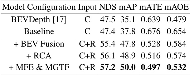
🔼 This table presents the ablation study results of the CRT-Fusion model. It shows the impact of adding key components sequentially to a baseline model. The baseline is BEVDepth [17]. The components added are BEV fusion, RCA (Radar-Camera Azimuth Attention), and finally MFE (Motion Feature Estimator) & MGTF (Motion Guided Temporal Fusion). The table displays the performance metrics (NDS, mAP, mATE, mAOE) for each configuration, demonstrating the contribution of each component to the overall performance improvement.
read the caption
Table 3: Ablation study of the main components of CRT-Fusion.
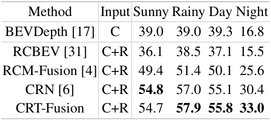
🔼 This table compares the performance of several 3D object detection methods under various weather and lighting conditions. The methods compared include BEVDepth, RCBEV, RCM-Fusion, CRN, and CRT-Fusion. The input sensor modalities are specified (C for camera only, C+R for camera and radar fusion). The mAP (mean Average Precision) results are shown for four different weather conditions: Sunny, Rainy, Day, and Night. The table highlights how the performance of the methods varies depending on these conditions.
read the caption
Table 4: Performance comparison under different weather and lighting conditions.

🔼 This table presents the ablation study results of the CRT-Fusion model. It shows the impact of adding each key component (BEV fusion, RCA, MFE & MGTF) on the model’s performance (NDS, mAP, mATE, MAOE). The baseline is BEVDepth, and each row adds one component to the previous model to evaluate their contributions to improved accuracy. ‘X’ indicates the component is included, while ‘O’ indicates it is excluded.
read the caption
Table 3: Ablation study of the main components of CRT-Fusion.

🔼 This table compares three different radar-based view transformation methods: RGVT, RVT, and RCA. The methods are evaluated based on their performance in 3D object detection using the nuScenes dataset. The metrics used for evaluation are NDS, mAP, mATE, mAOE, and mAVE. RCA, the method proposed by the authors, outperforms the existing methods in terms of NDS, mAOE, and mAVE.
read the caption
Table 6: Comparison of radar-based view transformation methods. RGVT: Radar-Guided View Transformer. RVT: Radar-assisted View Transformation.

🔼 This table compares the performance of different 3D object detection methods on the nuScenes validation dataset. The methods use various sensor combinations (LiDAR only, camera only, camera and radar). The table shows the performance metrics: NDS (NuScenes Detection Score), mAP (mean Average Precision), and several other metrics related to the accuracy of 3D bounding box estimation. It also indicates which methods used certain training techniques (CBGS and TTA).
read the caption
Table 1: Performance comparisons with 3D object detector on the nuScenes val set. 'L', 'C', and 'R' represent LiDAR, camera, and radar, respectively. †: trained with CBGS. ‡: use TTA.

🔼 This table compares the performance of various 3D object detection methods on the nuScenes validation set. It shows the NDS (NuScenes Detection Score), mAP (mean Average Precision), and other metrics (mATE, MASE, MAOE, MAVE, MAAE, FPS) for each method. Different sensor combinations (LiDAR only, camera only, camera-radar fusion) and backbone networks are used. The table also notes if a method used CBGS (class-balanced grouping and sampling) or TTA (test-time augmentation). The metrics evaluate the accuracy of the 3D bounding boxes predicted by each method for various object classes.
read the caption
Table 1: Performance comparisons with 3D object detector on the nuScenes val set. 'L', 'C', and 'R' represent LiDAR, camera, and radar, respectively. †: trained with CBGS. ‡: use TTA.

🔼 This table presents a comparison of the performance of different 3D object detection methods on the nuScenes validation set. The methods use various sensor combinations (LiDAR only, camera only, camera and radar). The table shows several metrics such as NDS (NuScenes Detection Score), mAP (mean Average Precision), and others to assess the accuracy of each method. The table also indicates which methods were trained with CBGS (class-balanced grouping and sampling) and those that used TTA (test-time augmentation).
read the caption
Table 1: Performance comparisons with 3D object detector on the nuScenes val set. ‘L’, ‘C’, and ‘R’ represent LiDAR, camera, and radar, respectively. †: trained with CBGS. ‡: use TTA.

🔼 This table compares the performance of different methods for 3D object detection on the nuScenes validation dataset. The methods use various sensor combinations (LiDAR only, camera only, camera-radar fusion). The table shows several metrics including NDS (nuScenes Detection Score), mAP (mean Average Precision), and several other metrics related to accuracy and precision. It also notes the backbone network used and the input image size. Abbreviations such as CBGS (Class Balanced Grouping and Sampling) and TTA (Test Time Augmentation) are explained in the paper.
read the caption
Table 1: Performance comparisons with 3D object detector on the nuScenes val set. 'L', 'C', and 'R' represent LiDAR, camera, and radar, respectively. †: trained with CBGS. ‡: use TTA.

🔼 This table presents a breakdown of the inference time for different components of the CRT-Fusion model. It compares the original CRT-Fusion model with a lightweight version (CRT-Fusion-light). The components are Camera Backbone (C.B.), Radar Backbone (R.B.), Multi-View Fusion (MVF), Motion Feature Estimation (MFE), Motion Guided Temporal Fusion (MGTF), and the detection Head. The total inference time is also given for each model. The lightweight version shows significantly faster inference times, primarily due to improvements in the Radar Backbone and MGTF modules.
read the caption
Table 11: Ablation study of Inference Time.
Full paper#


