↗ OpenReview ↗ NeurIPS Proc. ↗ Chat
TL;DR#
Classical optimization algorithms often prioritize worst-case convergence guarantees, leading to slow practical performance. Modern machine learning optimizers focus on empirical performance but often lack theoretical guarantees. This creates a significant challenge: balancing theoretical rigor with practical efficiency. The existing methods of designing optimization algorithms either prioritize speed, ignoring theoretical guarantees, or focus on theoretical guarantees, compromising on speed.
This paper presents a novel methodology using electric circuits to address this issue. It proposes to design an electric circuit whose dynamics converge to the optimization problem’s solution. Then, it leverages computer-assisted techniques to discretize the circuit’s continuous-time dynamics into a provably convergent discrete-time algorithm. This approach is shown to recover several classical algorithms and enables users to readily explore new ones with convergence guarantees.
Key Takeaways#
Why does it matter?#
This paper is significant because it offers a novel, systematic approach to designing optimization algorithms. It bridges the gap between theoretical guarantees and practical performance by using intuitive circuit analogies. This opens avenues for researchers to quickly design and explore a wider range of new algorithms with provable convergence, thus advancing both theoretical understanding and practical applications of optimization.
Visual Insights#
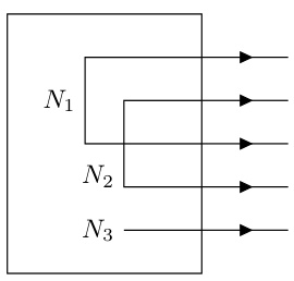
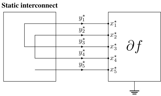
This figure illustrates a static interconnect, a simplified representation of a circuit where several terminals are connected to form different nets. The example shows five terminals (m=5) grouped into three nets (n=3): Net 1 (N1) connects terminals 1 and 3; Net 2 (N2) connects terminals 2 and 4; and Net 3 (N3) connects terminal 5. This structure represents a fundamental element in the proposed methodology for designing optimization algorithms using electrical circuit principles.
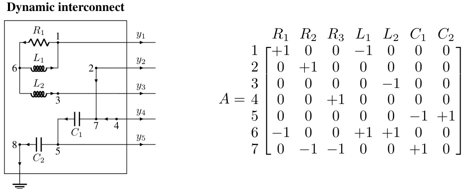
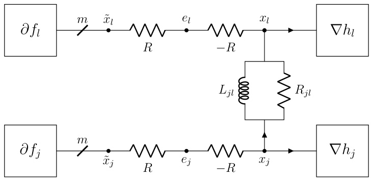
This figure shows an example of a dynamic interconnect, which is an RLC circuit with 8 nodes, 7 components, 5 terminals, and 1 ground node. The figure highlights the interconnect’s topology using a reduced node incidence matrix. The matrix shows the connections between nodes and components, with +1 indicating a connection to the positive terminal, -1 to the negative terminal, and 0 indicating no connection. Two of the resistors (R2 and R3) are 0-ohm resistors. The dynamic interconnect is designed to be admissible with the static interconnect shown in Figure 1, meaning it relaxes to the static interconnect’s configuration in equilibrium.
In-depth insights#
Circuit-Based Optim.#
The heading ‘Circuit-Based Optim.’ suggests a novel approach to optimization algorithm design that leverages principles and structures from electrical circuits. This methodology likely involves mapping optimization problems onto circuit components (resistors, capacitors, inductors), where the circuit’s dynamic behavior (voltage, current flow) mirrors the iterative solution process. The continuous-time dynamics of the circuit converge to the optimal solution, and discretization techniques are applied to create computationally tractable, discrete-time algorithms. A key advantage is the potential for automated algorithm design, where circuit synthesis tools could assist in generating new optimization algorithms. The approach might offer insights into algorithm stability and convergence properties through circuit analysis. Circuit theory provides a rich framework for understanding energy dissipation and system stability, which can be directly linked to the convergence behavior and performance of the optimization algorithm. However, limitations include the need for suitable circuit analogies for diverse optimization problems, and the complexity of analyzing and discretizing complex circuits.
Auto. Discretization#
The heading ‘Auto. Discretization’ suggests a method for automatically converting continuous-time optimization dynamics, represented by electric circuits, into discrete-time algorithms. This is crucial because continuous-time models are often easier to analyze for convergence properties, but real-world implementations require discrete steps. The paper likely details a systematic approach, potentially using numerical methods like Runge-Kutta, to achieve this discretization. A key aspect is ensuring that the discrete algorithm inherits the convergence guarantees of the continuous-time system. The authors might leverage performance estimation techniques to find parameters that guarantee this convergence. This automated approach contrasts with manual discretization, which can be tedious, error-prone, and less likely to preserve convergence properties. The process likely involves solving an optimization problem, perhaps a semidefinite program (SDP) or a quadratically constrained quadratic program (QCQP), to find optimal discretization parameters. The success of this method hinges on the ability to efficiently solve this optimization problem and ensure sufficient energy dissipation in the discretized system. The availability of an automated procedure significantly accelerates the design process and allows for easy exploration of a broader range of optimization algorithms.
Classical Alg. Rec.#
The heading ‘Classical Alg. Rec.’ likely refers to a section in the research paper that revisits and analyzes classical optimization algorithms through the lens of electric circuits. The authors likely demonstrate how these established algorithms, such as gradient descent or proximal methods, can be represented as or derived from the dynamics of specific RLC circuits. This approach offers novel interpretations of familiar algorithms, potentially highlighting underlying connections and providing new perspectives on their behavior. A key aspect would be showing how the continuous-time dynamics of the circuit translate into the discrete-time updates of the algorithm, possibly revealing new discretization strategies or providing a unifying framework. The analysis might involve deriving the algorithms’ convergence properties directly from the circuit’s stability and energy dissipation characteristics. Furthermore, the authors could use this circuit-based representation to design new optimization algorithms, starting from novel circuit topologies and analyzing their behavior in the continuous-time domain before discretizing them. This is significant because it allows for creating algorithms with provable convergence properties while providing intuitive ways to design and modify algorithms. Overall, this section likely provides a bridge between classical optimization theory and the electric circuit framework, offering fresh insights and potentially new algorithm designs.
DADMM+C Variant#
The DADMM+C variant, a modification of the Decentralized Alternating Direction Method of Multipliers (DADMM), is a notable contribution because it leverages the strong convexity of certain functions within the optimization problem. By incorporating additional capacitors into the circuit model, the algorithm is designed to accelerate convergence, which is particularly beneficial when dealing with strongly convex components. This modification is not merely an arbitrary addition but a principled approach stemming from the inherent properties of circuits with capacitors and their relationship to momentum methods. The addition of capacitors creates dynamics within the circuit that implicitly introduce a momentum term, enhancing the algorithm’s ability to converge quickly, especially when certain functions exhibit strong convexity. The authors provide a thorough theoretical analysis, demonstrating the dissipative properties of the DADMM+C variant and establishing convergence guarantees. Experimental results show that DADMM+C outperforms standard DADMM and PG-EXTRA, demonstrating the practical value of this enhancement. However, the effectiveness might depend on the specifics of the problem’s structure and the characteristics of its component functions. Further investigation is needed to thoroughly assess its robustness and generalizability across a wider range of optimization problems.
Future Research#
The paper’s “Future Research” section would ideally explore extending the proposed methodology to a broader range of optimization problems. Stochastic optimization, where objective function evaluations are noisy, presents a compelling avenue for investigation. Adapting the circuit framework to handle noisy signals and incorporating noise-robust discretization techniques would be a significant contribution. Another promising area lies in non-convex optimization. The paper focuses on convex problems; extending the methodology to handle non-convexity, perhaps through techniques like adding penalty terms or incorporating specialized circuit components, would be highly impactful. Finally, developing more sophisticated automatic discretization methods beyond the current Runge-Kutta approach, perhaps using adaptive step-size techniques or higher-order methods, could improve efficiency and accuracy. Investigating the theoretical convergence rates for various discretization schemes and characterizing the trade-off between accuracy and computational cost would also strengthen the work.
More visual insights#
More on figures
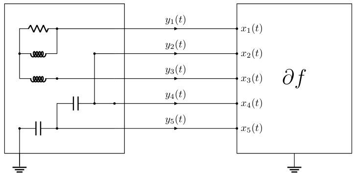
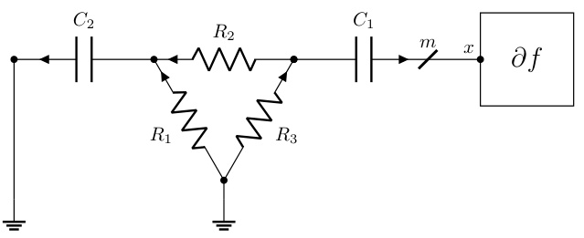
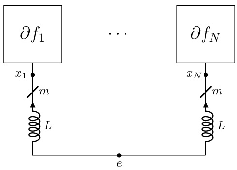
This figure shows a dynamic interconnect (from Figure 2) connected to a nonlinear resistor representing the subdifferential operator ∂f of a convex function f. The continuous-time dynamics of this circuit are shown to converge to the optimal solution x* of the optimization problem (1) under specific conditions (stated in Theorem 2.2). The potentials x(t) at the m terminals represent the evolution of the optimization variable over time, converging towards the optimal solution x*. This illustrates the core idea of the paper: designing electric circuits whose dynamics solve convex optimization problems.

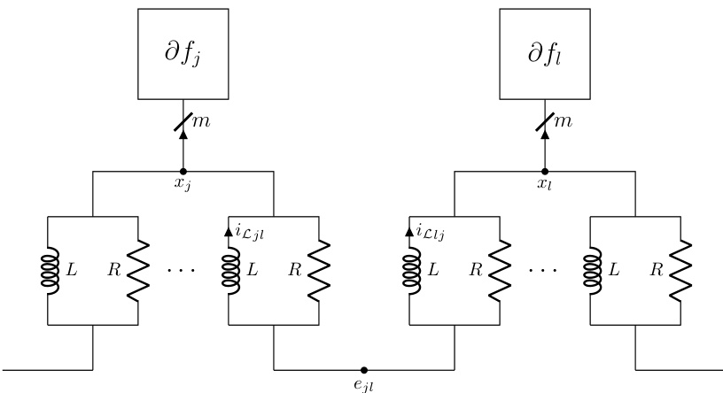
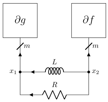
The figure shows a multi-wire notation for simplifying the representation of circuits with multiple identical RLC components. Each diagonal line represents the m identical copies of the same RLC circuit used in the m coordinates of the variable x ∈ Rm. This notation is useful when describing circuits for the m-terminal device ∂f.

This figure shows a static interconnect from Figure 1 connected to a nonlinear resistor representing the subdifferential of a convex function. The static interconnect enforces consensus among the primal variables, represented by the potentials at the terminals. The connection to the subdifferential ensures that the potentials at the terminals converge to an optimal solution x* of the optimization problem (1) described in the paper. The figure illustrates that the KKT (Karush-Kuhn-Tucker) conditions are satisfied at the optimal solution, indicating that the static circuit directly solves the optimization problem.

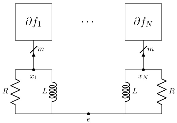
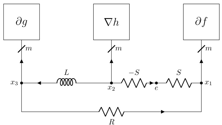
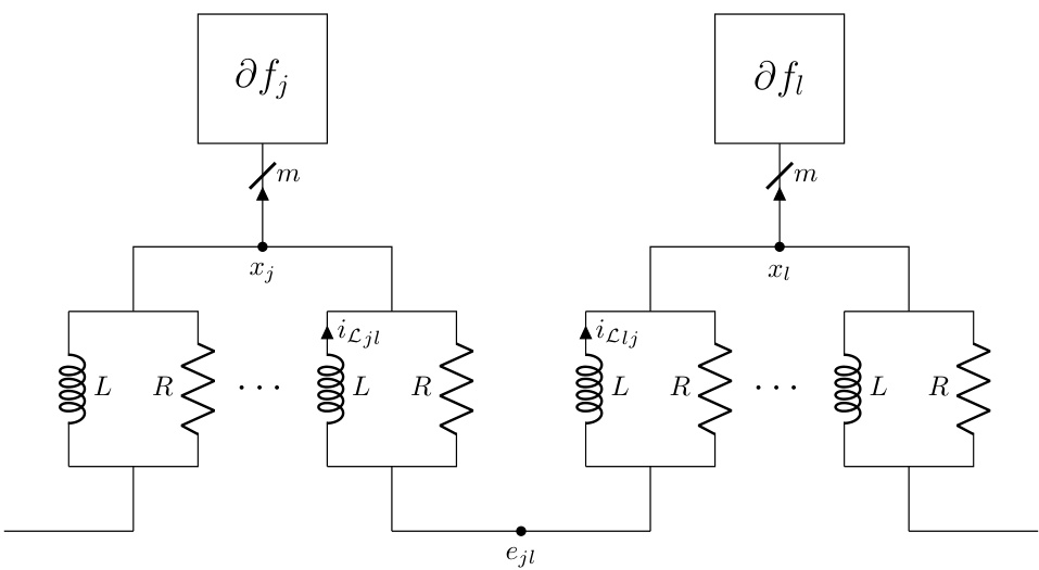
This figure shows a dynamic interconnect circuit from Figure 2 connected to a nonlinear resistor representing the subdifferential operator ∂f of a convex function. The circuit’s dynamics, governed by the interaction of resistors, inductors, capacitors, and the nonlinear resistor, are designed to converge to the optimal solution x* of the optimization problem (1). Theorem 2.2 provides conditions under which this convergence is guaranteed.
This figure shows a static interconnect (from Figure 1) connected to a nonlinear resistor representing the subdifferential of a convex function (∂f). The static interconnect consists of ideal wires that enforce Kirchoff’s laws, ensuring that the terminal potentials (x) satisfy the constraints of the optimization problem. Connecting the subdifferential operator enforces the optimality condition y ∈ ∂f(x), where y represents the currents at the terminals. The potentials (x*) at the terminals represent the optimal solution to the convex optimization problem.
This figure shows a dynamic interconnect (an RLC circuit) connected to a nonlinear resistor representing the subdifferential of a convex function. The circuit’s terminals are connected to the inputs of the subdifferential operator. The figure illustrates the continuous-time dynamics of the circuit converging to the optimal solution x* of the optimization problem (as stated in Theorem 2.2), demonstrating the core concept of the proposed optimization algorithm design methodology.
This figure shows a static interconnect circuit connected to a nonlinear resistor representing the subdifferential of a convex function, ∂f. The static interconnect consists of ideal wires connecting terminals to form nets, which enforces Kirchhoff’s voltage and current laws. Connecting this static interconnect to ∂f imposes the optimality condition, and the resulting potentials at the terminals represent the optimal solution (x*) to the standard-form convex optimization problem presented in the paper. This circuit is static; it does not change over time.
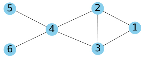
This figure shows the underlying graph G used in the decentralized optimization problem described in Section 5 of the paper. The graph has 6 nodes (agents) and 7 edges representing the communication links between them. The nodes are numbered 1 through 6, and the edges connect certain pairs of nodes, indicating how information can be exchanged between the agents in the distributed optimization setting. The structure of this graph is important as it determines the way the decentralized algorithm operates.
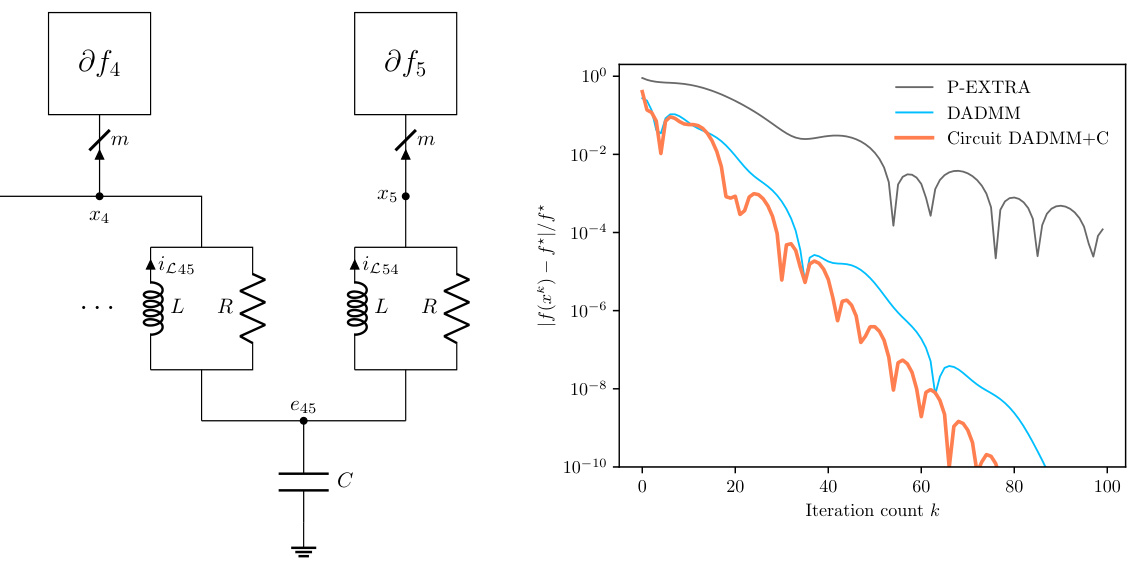
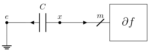
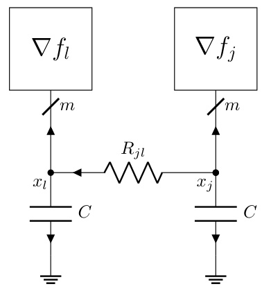
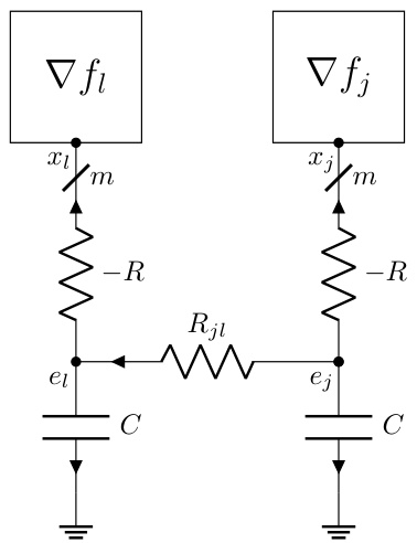
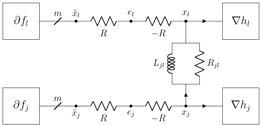
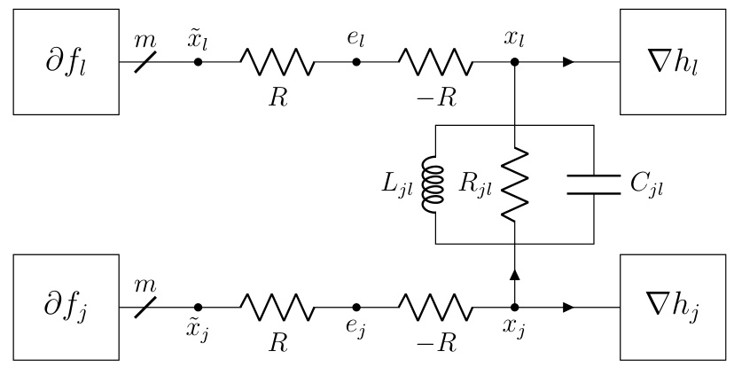
The figure shows two subfigures. The left subfigure is a circuit diagram that adds a capacitor to the DADMM circuit in §F.3. The right subfigure is a plot that compares the convergence speed of three algorithms: DADMM, P-EXTRA, and DADMM+C. DADMM+C shows faster convergence.
This figure shows a static interconnect from Figure 1 connected to a nonlinear resistor representing the subdifferential of a convex function (\partial f). The static interconnect enforces the constraints of the optimization problem, while the nonlinear resistor represents the objective function. The figure illustrates that the potentials at the terminals of the combined circuit represent the optimal solution (x*) to the optimization problem.
This figure shows a static interconnect (from Figure 1) connected to a nonlinear resistor representing the subdifferential of the objective function, (\partial f). The static interconnect enforces the constraint (x \in \mathcal{R}(E^T)), and the nonlinear resistor ensures that the current (y) satisfies (y \in \partial f(x)). The combination of these results in the system converging to the optimal primal-dual solution ((x^, y^)) that satisfies the Karush-Kuhn-Tucker (KKT) conditions for the optimization problem. The potentials at the terminals represent the optimal solution (x^*).
This figure shows a circuit diagram where a static interconnect (a set of ideal wires connecting terminals and forming nets) is connected to a nonlinear resistor representing the subdifferential of a convex function (∂f). The potentials at the m terminals of the circuit represent the optimal solution (x*) to the convex optimization problem (1) formulated in the paper. The interconnection enforces the optimality condition (3).

This figure shows a static interconnect (a set of ideal wires connecting terminals and forming n nets) connected to a nonlinear resistor representing the subdifferential of a convex function (∂f). The static interconnect enforces Kirchhoff’s voltage and current laws, resulting in the potentials at the m terminals converging to the optimal solution (x*) of the standard-form convex optimization problem (1) described in the paper. This demonstrates how a simple circuit can solve an optimization problem.
This figure illustrates the concept of connecting a static interconnect (a set of ideal wires) with a nonlinear resistor representing the subdifferential of a convex function. The static interconnect enforces Kirchhoff’s voltage and current laws, effectively imposing constraints on the system. Connecting this with the nonlinear resistor representing the subdifferential (∂f) creates a circuit whose equilibrium point corresponds to the optimal solution (x*) of the convex optimization problem. The potentials at the m terminals of the ∂f element will converge to the optimal solution x* of the optimization problem, as defined by the optimality conditions.
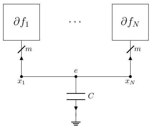
This figure illustrates the static interconnect from Figure 1 connected with the subdifferential operator ∂f. The static interconnect consists of ideal wires connecting terminals and forming nets, enforcing Kirchhoff’s voltage and current laws. Connecting this to ∂f, which represents an m-terminal electric device, enforces the optimality condition which ensures the potentials at the terminals (x*) represent the optimal solution of the standard-form optimization problem in equation (1).
This figure shows the underlying graph G used in the decentralized optimization problem in Section 5. The graph has 6 nodes and 7 edges, representing the communication structure between agents in the distributed system. Each node represents an agent, and an edge indicates a direct communication link between two agents. The topology of this graph affects the performance of decentralized algorithms.
This figure shows the underlying communication graph G used in the decentralized optimization problem in Section 5. The graph has 6 nodes (representing agents) and 7 edges (representing communication links between agents). The nodes are numbered 1 through 6. The edges connect pairs of nodes, illustrating the communication topology for the distributed optimization task.
The figure shows two plots. The left plot is a schematic diagram of the DADMM+C circuit, which is a modification of the DADMM circuit from section F.3 of the paper, with an additional capacitor added to improve performance for strongly convex functions. The right plot shows the convergence rate of three different algorithms: DADMM, P-EXTRA, and DADMM+C, in solving a decentralized optimization problem. The y-axis represents the relative error, and the x-axis represents the iteration count. The plot illustrates that the DADMM+C algorithm converges faster than DADMM and P-EXTRA.
This figure shows a static interconnect from Figure 1 connected with a nonlinear resistor representing the subdifferential operator ∂f. The static interconnect consists of ideal wires connecting terminals to form nets. The connection of the static interconnect with ∂f enforces the optimality conditions, resulting in the potentials at the m terminals representing the optimal solution x* of the standard-form optimization problem (1).
This figure depicts a static interconnect, a simplified representation of an electric circuit. It shows five terminals (m=5) connected by wires to form three nets (n=3). Each net represents a group of terminals with the same potential. Net N₁ connects terminals 1 and 3, N₂ connects terminals 2 and 4, and N₃ connects terminal 5. This illustrates how a network of terminals can be interconnected to enforce consensus – in this case, terminals within each net must have identical potentials.
This figure shows a static interconnect (a set of ideal wires connecting terminals and forming n nets) connected to a nonlinear resistor that represents the subdifferential of a convex function (∂f). The potentials at the m terminals of the interconnect represent the solution (x*) to the standard-form convex optimization problem presented earlier in the paper. The static nature implies that the circuit reaches equilibrium, with the potentials and currents not changing over time.
This figure shows a static interconnect from Figure 1 connected to a nonlinear resistor representing the subdifferential of a convex function (∂f). The static interconnect enforces consensus among the primal variables. The potentials (x*) at the m terminals represent the optimal solution to the standard-form optimization problem (1) described in the paper. This is because the interconnect enforces the optimality conditions, thus the circuit will relax to the optimal solution.
This figure shows a dynamic interconnect, which is an RLC circuit with m terminals and 1 ground node, connected to the subdifferential operator ∂f. The continuous-time dynamics of this circuit, under appropriate conditions, converge to an optimal solution x* of the optimization problem (1). The potentials at the m terminals represent the optimization variable x, and the currents flowing into the terminals represent the gradient of the objective function. The circuit’s behavior is governed by Kirchhoff’s laws and the constitutive relations of the RLC components (resistors, inductors, capacitors), and the non-linear resistor representing ∂f.
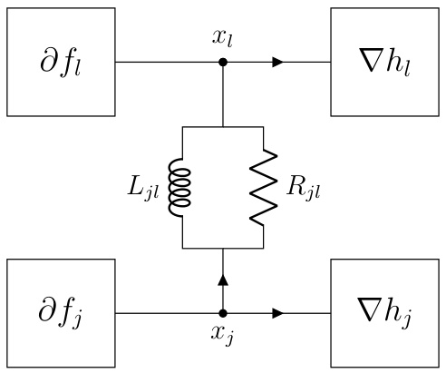
This figure shows the static interconnect from Figure 1 connected with the subdifferential operator ∂f. The static interconnect is represented by a set of wires connecting terminals and forming nets. It enforces Kirchhoff’s voltage and current laws. The subdifferential operator ∂f represents a nonlinear resistor, connected to the m terminals. This combination results in a static circuit, the potentials at the m terminals representing the optimal solution x* of the optimization problem. The optimization problem is given by: minimize f(x) subject to x ∈ R(Eᵀ), where x ∈ Rᵐ is the optimization variable, f: Rᵐ → R ∪ {∞} is closed, convex and proper, and E ∈ Rⁿˣᵐ.
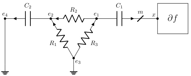
This figure shows a dynamic interconnect circuit with resistors, inductors, and capacitors connected to a nonlinear resistor representing the subdifferential of a convex function. The potentials at the terminals of the circuit converge to the optimal solution of a convex optimization problem under certain conditions specified in Theorem 2.2 of the paper. The circuit’s dynamics are governed by differential equations which, upon discretization, lead to a provably convergent optimization algorithm.
This figure shows the relative error in the objective function value across iterations when applying the new algorithm described in the paper. The algorithm is applied to a random problem instance with a Huber penalty function, and the relative error is plotted against the iteration number. The figure demonstrates the convergence of the new algorithm.
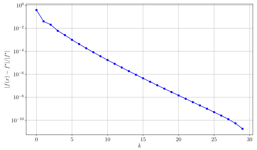
This figure shows the convergence of a new optimization algorithm on a test problem involving the Huber loss function. The y-axis is a log scale showing the relative error in the objective function value at each iteration (k) and demonstrates that the algorithm converges rapidly to a solution.
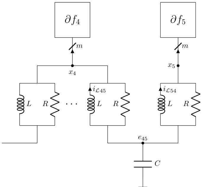
The left part of the figure shows the circuit diagram of DADMM+C, a modification of the DADMM circuit from section F.3, which incorporates an additional capacitor to leverage the strong convexity of some functions. The right part displays a plot illustrating the convergence of the DADMM+C algorithm, comparing its relative error |f(xk) – f*|/f* against iteration count (k). This is compared with DADMM and P-EXTRA algorithms.
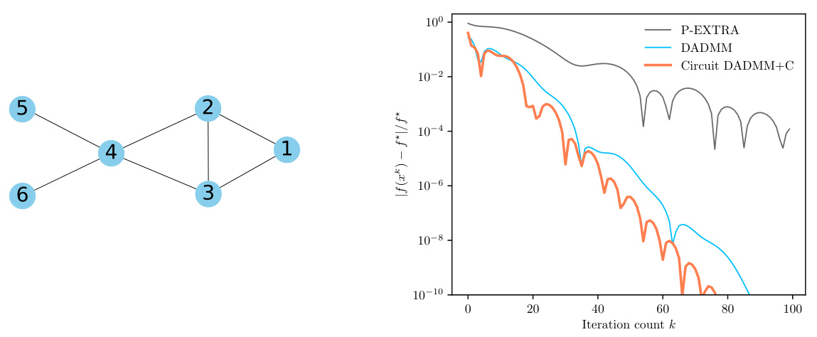
The left panel shows the underlying graph G used in the decentralized optimization problem. The right panel displays the convergence performance of three different algorithms: DADMM+C (the new algorithm proposed in the paper), DADMM, and P-EXTRA. The y-axis represents the relative error, |f(xk) - f*|/f*, where f(xk) is the objective function value at iteration k and f* is the optimal value. The x-axis represents the iteration number k. The plot demonstrates that the DADMM+C algorithm converges faster than DADMM and P-EXTRA, reaching a relative error of 10⁻¹⁰ in fewer iterations.
This figure shows a dynamic interconnect, which is an RLC circuit with m terminals and a ground node, connected to a nonlinear resistor representing the subdifferential of a convex function. The potentials at the m terminals represent the optimization variable x. The figure illustrates how the continuous-time dynamics of the circuit converge to an optimal solution x* that satisfies the optimality condition (3) under the specific conditions mentioned in Theorem 2.2 of the paper.
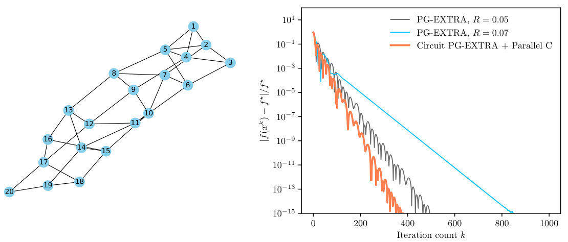
The figure on the left shows the underlying graph G used in the decentralized optimization problem. The graph has 20 nodes and edges connecting them. The figure on the right displays the relative error |f(xk) – f*|/f* across iterations k for three different algorithms: PG-EXTRA with R = 0.05, PG-EXTRA with R = 0.07, and Circuit PG-EXTRA + Parallel C. The plot demonstrates how the Circuit PG-EXTRA + Parallel C algorithm converges faster to the optimal solution compared to the other two algorithms.
More on tables
This figure shows the relative error |f(xk) - f*|/f* plotted against the iteration number k, demonstrating the convergence of the new algorithm proposed in the paper. The algorithm is applied to a randomly generated problem instance with a Huber penalty function. The plot illustrates that the algorithm efficiently reduces the error over iterations.

This figure shows the relative error (f(x) - f*)/f* plotted against the number of iterations (k) for a new algorithm proposed in the paper. It demonstrates the convergence of the algorithm towards the optimal solution for a specific problem instance involving a Huber penalty function.

This figure shows the relative error across iterations when applying the new algorithm proposed in the paper. The algorithm solves a dual problem using the Huber penalty function, a convex function with bounded smoothness (2-smooth). The problem parameters (m, n) are set to (30, 100), and entries of A, c, and b are sampled from an i.i.d. Gaussian distribution. The figure demonstrates the algorithm’s convergence behavior in terms of relative error.

This figure shows the relative error between the objective function value at each iteration and the optimal objective function value, when applying the new algorithm proposed in the paper. The plot shows that the relative error decreases as the number of iterations increases, demonstrating the convergence of the algorithm.

This figure shows the relative error (f(x_k) - f*)/f* plotted against the iteration number (k) for a new algorithm derived from the methodology described in the paper. The algorithm is applied to a random problem instance with a Huber penalty function, and the results demonstrate the convergence properties of the algorithm.

This figure shows the relative error across iterations for a new algorithm applied to a random problem instance. The algorithm is based on the methodology presented in the paper, which uses electric circuits to design optimization algorithms. The y-axis represents the relative error, and the x-axis represents the iteration number. The plot demonstrates the convergence of the new algorithm to the optimal solution.
Full paper#


